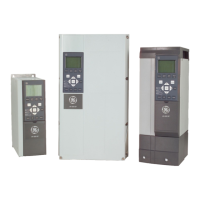
Illustration 6.9: Space in front of IP21/Nema 1 and IP54/Nema
drive types for unit size 61
Illustration 6.10: Space in front of IP21/Nema 1 and IP54/Nema
drive types for unit size 63
Illustration 6.11: Space in front of IP21/Nema 1 and IP54/Nema
drive types for unit size 62
Illustration 6.12: Space in front of IP21/Nema 1 and IP54/Nema
drive types for unit size 64
Wire access
Ensure that proper cable access is present including necessary bending allowance. As the IP00 Open Chassis drive type is open to the bottom cables must be
fixed to the back panel of the Unit where the frequency converter is mounted, i.e. by using cable clamps.
NB!
All cable lugs/ shoes must mount within the width of the terminal bus bar
AF-650 GP Design Guide
104
6

 Loading...


