9 Options and Accessories
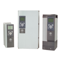
GE offers a wide range of options and accessories for AF-650 GP.
9.1.1 Mounting of Option Modules in Slot A
Slot A position is dedicated to Network options. For further information, see separate operating instructions.
9.1.2 Mounting of Option Modules in Slot B
The power to the frequency converter must be disconnected.
It is strongly recommended to make sure the parameter data is saved (i.e. by DCT10 software ) before option modules are inserted/removed from the drive.
• Remove the Keypad, the terminal cover, and the Keypad frame from the frequency converter.
• Fit the OPCxxx option card into slot B.
• Connect the control cables and relieve the cable by the enclosed cable strips.
* Remove the knock out in the extended Keypad frame, so that the option will fit under the extended Keypad frame.
• Fit the extended Keypad frame and terminal cover.
• Fit the Keypad or blind cover in the extended Keypad frame.
• Connect power to the frequency converter.
• Set up the input/output functions in the corresponding parameters, as mentioned in the section General Technical Data.
Unit Sizes 12, 13 and 23 Unit Sizes 15, 21, 22, 24, 31, 32, 33 and 34
AF-650 GP Design Guide
167
9

 Loading...


