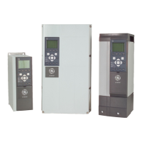
Installation of field installed 24 Volt external DC Supply option module (OPC24VPS)
Torque: 0.5 - 0.6 Nm (5 in-lbs)
Screw size: M3
No.
Function
35 (-), 36 (+) 24 V external DC supply
24 VDC external supply can be used as low-voltage supply to the control card and any I/O or network option cards installed. This enables full operation of the
Keypad (including parameter setting) without connection to mains. Please note that a warning of low voltage will be given when 24 VDC has been connected;
however, there will be no tripping.
Use 24 VDC supply of type PELV to ensure correct galvanic isolation (type PELV) on the control terminals of the frequency converter.
7.6.3 Control Terminals
Control Terminals, AF-650 GP
Drawing reference numbers:
1. 8 pole plug digital I/O.
2. 3 pole plug RS485 Bus.
3. 6 pole analog I/O.
4. USB Connection.
Control Terminals, AF-650 GP
Drawing reference numbers:
1. 10 pole plug digital I/O.
2. 3 pole plug RS485 Bus.
3. 6 pole analog I/O.
4. USB Connection.
Illustration 7.33: Control terminals (all Unit Sizes)
AF-650 GP Design Guide
143
7

 Loading...


