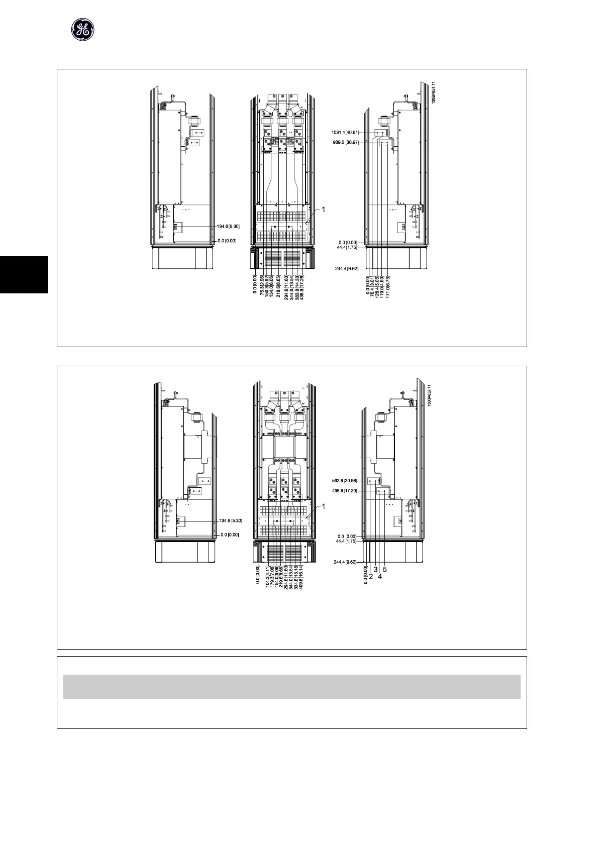
Terminal locations - Options Cabinet (Unit Sizes 63 and 64)
Illustration 6.22: Terminal locations - Options Cabinet (Left side, front and right side view). The gland plate is 42 mm below .0 level.
1) Ground bar
Terminal locations - Options Cabinet with circuit breaker/ molded case switch (Unit Sizes 63 and 64)
Illustration 6.23: Terminal locations - Options Cabinet with circuit breaker/ molded case switch (Left side, front and right side view). The gland plate
is 42 mm below .0 level.
1) Ground bar
Power size 2345
450 kW (480 V), 630-710 kW (690
V)
34.9 86.9 122.2 174.2
500-800 kW (480 V), 800-1000
kW (690 V)
46.3 98.3 119.0 171.0
Table 6.2: Dimension for terminal
AF-650 GP Design Guide
110
6

 Loading...


