6.2.7 Installation on the Wall - IP21 (NEMA 1) and IP54 (NEMA 12) Units
This only applies to 41 and 42 Unit Sizes (460V, 125 - 300 HP, 575/600V, 125 - 400 HP). It must be considered where to install the unit.
Take the relevant points into consideration before you select the final installation site:
• Free space for cooling
• Access to open the door
• Cable entry from the bottom
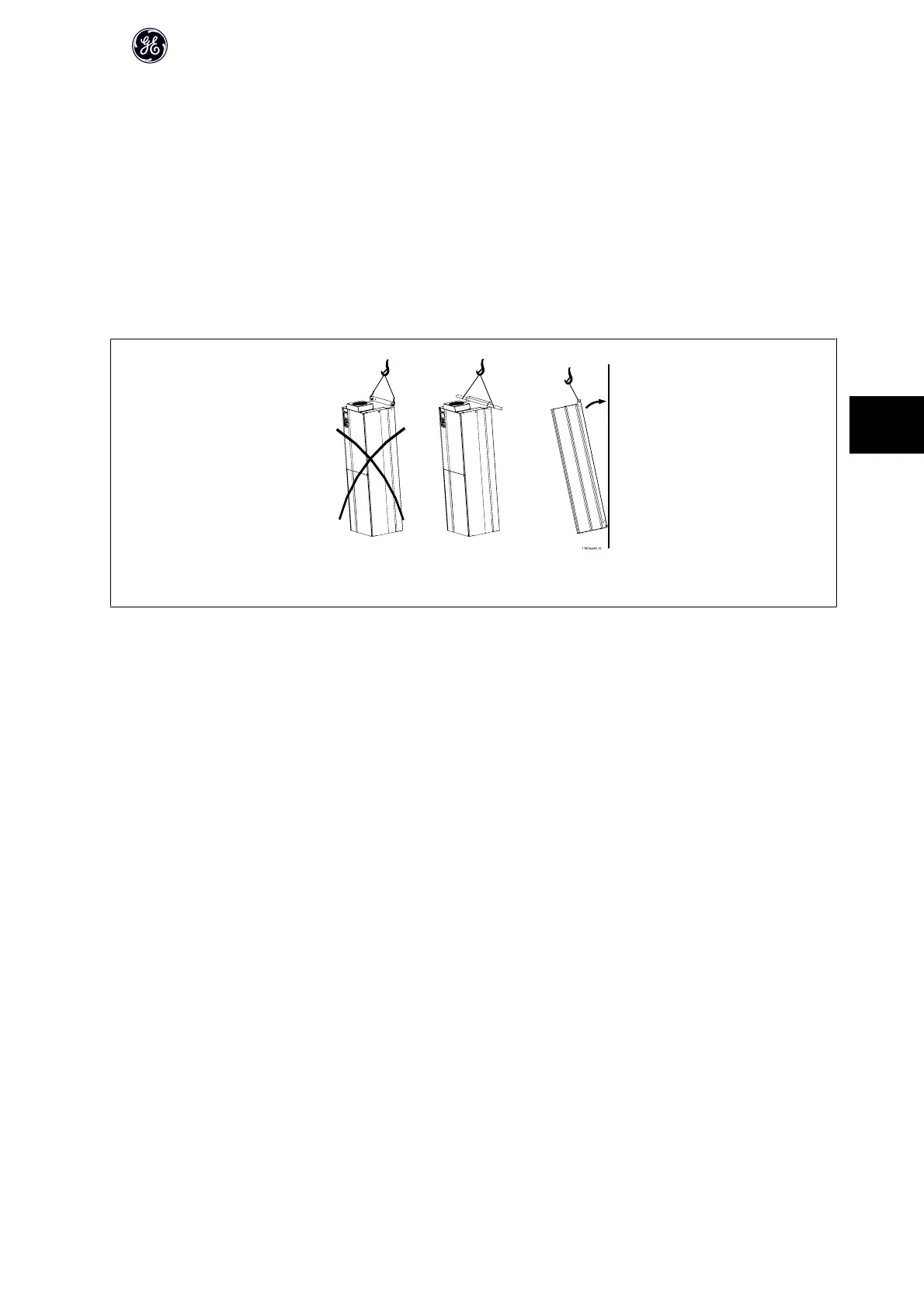
Mark the mounting holes carefully using the mounting template on the wall and drill the holes as indicated. Ensure proper distance to the floor and the ceiling for
cooling. A minimum of 225 mm (8.9 inch) below the frequency converter is needed. Mount the bolts at the bottom and lift the frequency converter up on the bolts.
Tilt the frequency converter against the wall and mount the upper bolts. Tighten all four bolts to secure the frequency converter against the wall.
Illustration 6.28: Lifting method for mounting drive on wall
AF-650 GP Design Guide
113
6

 Loading...


