12, 13, 23 15, 21, 22, 24, 31, 32, 33, 34
1)
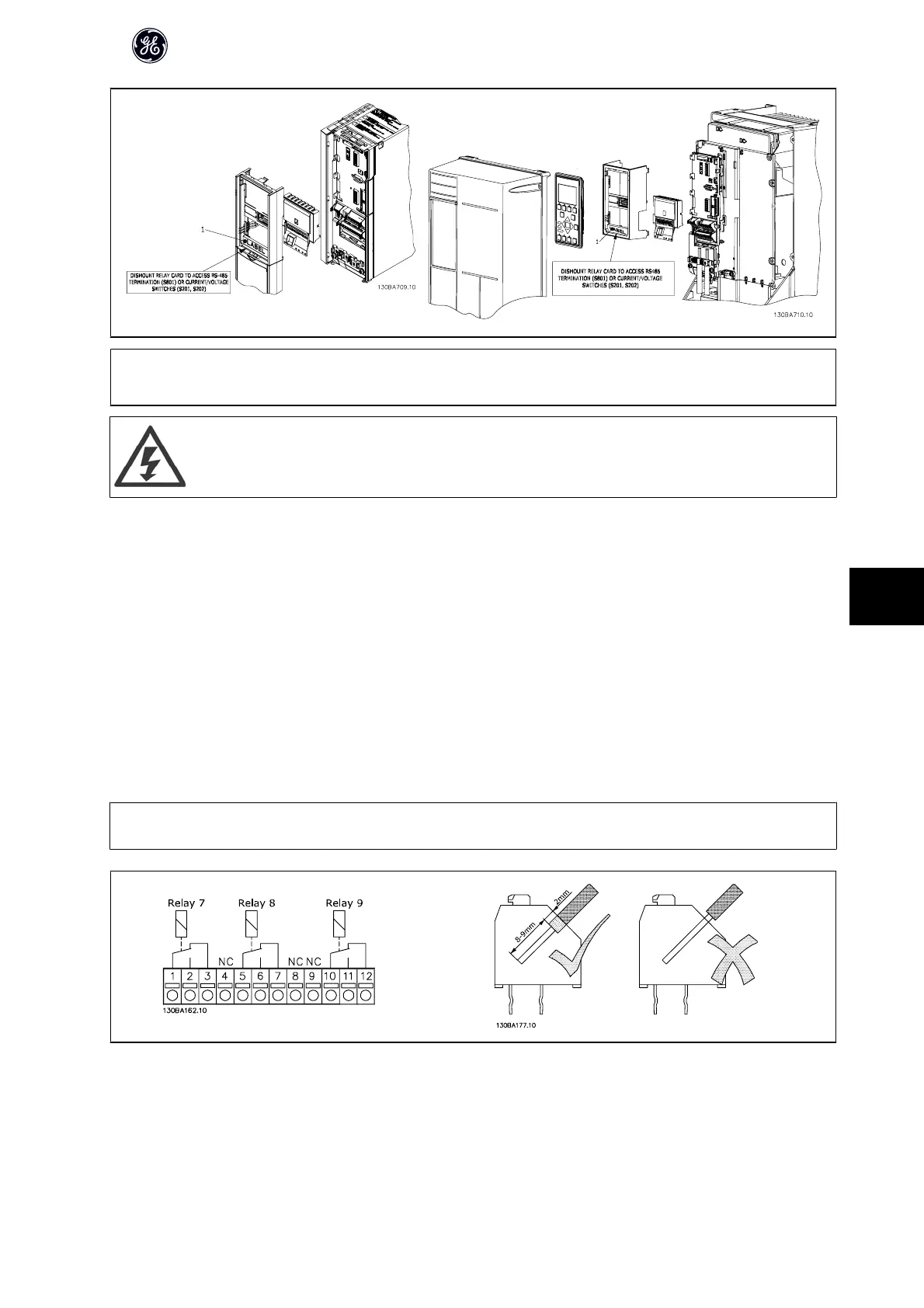
IMPORTANT ! The label MUST be placed on the Keypad frame as shown (UL approved).
Warning Dual supply
How to add the OPCRLY Relay Option Module:
• The power to the frequency converter must be disconnected.
• The power to the live part connections on relay terminals must be disconnected.
• Remove the Keypad, the terminal cover and the Keypad fixture from the frequency converter.
• Fit the OPCRLY Relay Option Module in slot B.
• Connect the control cables and fasten the cables with the enclosed cable strips.
• Make sure the length of the stripped wire is correct (see the following drawing).
• Do not mix live parts (high voltage) with control signals (PELV).
• Fit the enlarged Keypad fixture and enlarged terminal cover.
•Replace the Keypad.
• Connect power to the frequency converter.
• Select the relay functions in par. E-24 Function Relay [6-8], par. E-26 On Delay, Relay [6-8] and par. E-27 Off Delay, Relay [6-8].
NB!
Array [6] is relay 7, array [7] is relay 8, and array [8] is relay 9
AF-650 GP Design Guide
175
9

 Loading...


