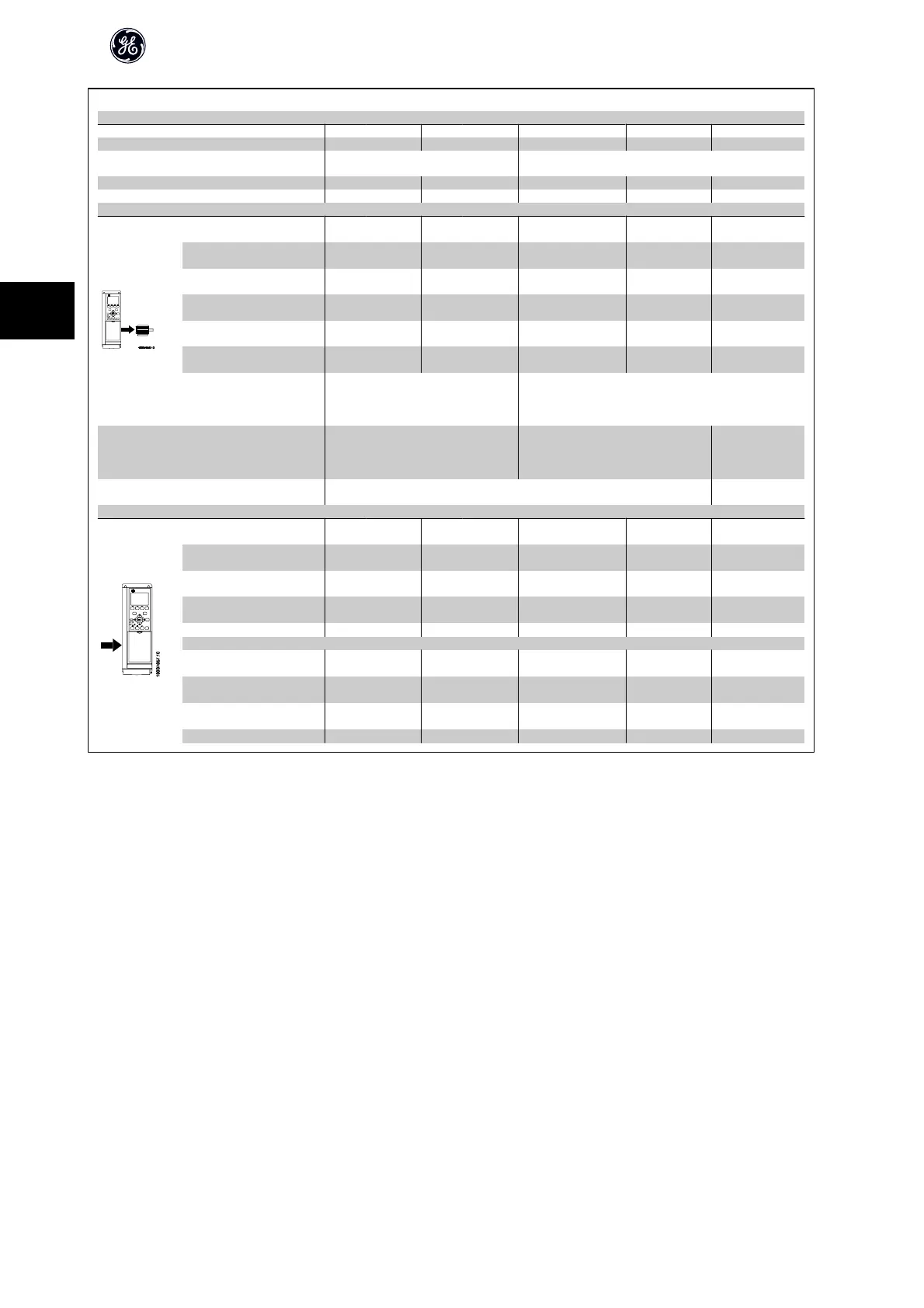
Mains Supply 3 x 525 - 600 VAC
AF-650 GP 15 HP 20 HP 25 HP 30 HP 40 HP
High/ Normal Load*
HD LD HD LD HD LD HD LD HD LD
Typical Shaft Output [kW] 11 15 15 18.5 18.5 22 22 30 30 37
Typical Shaft Output [HP] at
575V
15 20 20 25 25 30 30 40 40 50
Unit Size IP 55, 66 21 21 22 22 31
Unit Size IP20 23 23 24 24 24
Output current
Continuous
(3 x 525-550 V ) [A]
19 23 23 28 28 36 36 43 43 54
Intermittent
(3 x 525-550 V ) [A]
30 25 37 31 45 40 58 47 65 59
Continuous
(3 x 525-600 V ) [A]
18 22 22 27 27 34 34 41 41 52
Intermittent
(3 x 525-600 V ) [A]
29 24 35 30 43 37 54 45 62 57
Continuous kVA (550 V AC)
[kVA]
18.1 21.9 21.9 26.7 26.7 34.3 34.3 41.0 41.0 51.4
Continuous kVA (575 V AC)
[kVA]
17.9 21.9 21.9 26.9 26.9 33.9 33.9 40.8 40.8 51.8
Max. cable size IP20
(mains, motor, load share and
brake)
[AWG]
2)
[mm
2
]
16(6) 35(2)
Max. cable size IP21, 55, 66
(mains, motor, load share and
brake)
[AWG]
2)
[mm
2
]
16(6) 35(2) 90 (3/0)
Max cable size with mains dis-
connect
16(6) 35(2)
Max. input current
Continuous
at 550 V [A]
17.2 20.9 20.9 25.4 25.4 32.7 32.7 39 39 49
Intermittent
at 550 V [A]
28 23 33 28 41 36 52 43 59 54
Continuous
at 575 V [A]
16 20 20 24 24 31 31 37 37 47
Intermittent
at 575 V [A]
26 22 32 27 39 34 50 41 56 52
Max. mains fuses
1)
[A]
63 63 63 80 100
Environment
Estimated power loss
at rated max. load [W]
4)
225 285 329 700 700
Weight,
Unit Size , IP55, 66 [kg]
23 23 27 27 27
Weight,
Unit Size IP20 [kg]
12 12 23.5 23.5 23.5
Efficiency
4)
0.98 0.98 0.98 0.98 0.98
AF-650 GP Design Guide
62
4

 Loading...


