8 Disassembly/Assembly - Inverter Module
8.1 For Your Safety
8.1.1 GE Training Required
Only GE trained and certified technicians are permitted to test and repair components within the unit modules. The procedures described in
this section are intended for GE qualified technicians. Repair work conducted by non-certified technicians can result in personal injury or
equipment damage.
8.2 Inverter Module
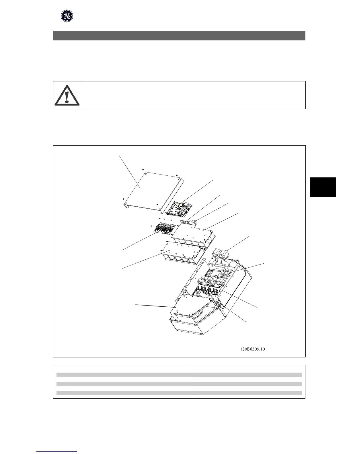
8.2.1 Inverter Module, Exploded View
1
2
3
4
5
6
7
8
9
10
11
12
1 Right side cover plate 7 High frequency board
2 Inverter power card 8 IGBT module
3 Panel connectors 9 Current sensor
4 SMPS fuse and fan fuse 10 Fan assembly
5 Upper capacitor bank assembly 11 Lower capacitor bank assembly
6 DC bus fuses 12 Gate driver card
High Power Service Manual for Unit Sizes 6x
111
8