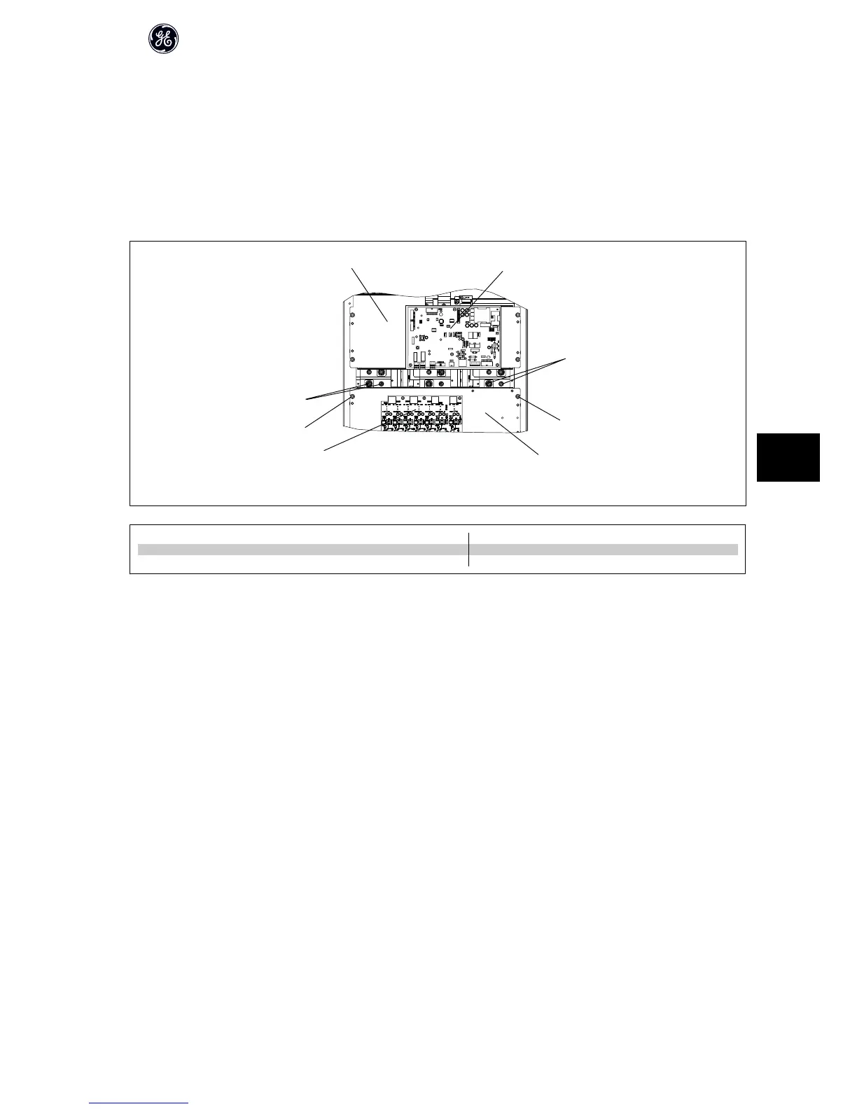
8.2.5 Lower Capacitor Bank Assembly
1. Disconnect cables from gate drive card connectors MK100, MK102, MK103, MK104, MK106, and, if unit has a brake option MK105.
2. Remove six electrical connection nuts (8mm) securing capacitor bank assembly. These nuts are recessed in the gap between the upper and lower
capacitor banks.
3. Remove four retaining nuts (10mm) securing capacitor bank assembly.
4. NOTE: Capacitor bank assembly may weigh up to 9 kg (20 lbs). Remove capacitor bank assembly.
Reassembly is done in reverse order.
1
2
3
3
4
4
5
6
130BX264.10
1 Upper capacitor bank assembly 4 10mm retaining nut (step 3)
2 Inverter power card 5 Lower capacitor bank assembly
3 8mm electrical connection nut (step 2) 6 IGBT gate driver card (step 1)
High Power Service Manual for Unit Sizes 6x
113
8