6.3.9 Gate Signal Test
1. Remove the output bus bars from all inverter modules.
2. Power drive in split bus mode. (See split bus powering).
3. Connect a 24VDC power supply to the (+) and (-) DC bus bars.
4. Connect the signal test board (p/n 6KAF6H8437) to the 30 pin connector at the top of the inverter module.
5. Apply a run command and a speed command above 0 RPM. (Hand Start mode is sufficient).
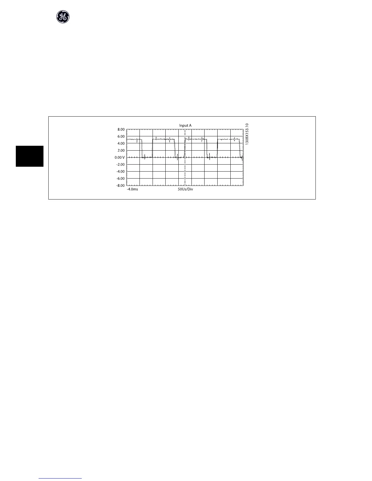
6. Connect the common lead of an oscilloscope to terminal 4 of the signal test board. Observe the waveform on terminals 25 – 30 in turn. Each reading
should appear similar to the figure shown.
7. Repeat this procedure for each inverter module.
Incorrect reading
If one or more of the IGBT gate signals is missing, this indicates a faulty connection in the ribbon cable from the control card to the MDCIC or from the MDCIC to
the inverter module. Check the cables and replaced if necessary. If all six signals are missing, the control card is likely defective and needs to be replaced.
Conduct the IGBT Switching Test with the frequency converter powered as in this procedure.
High Power Service Manual for Unit Sizes 6x
88
6