4.6. ControlTerminalWiring
• Allanalogsignalcablesshouldbesuitablyshielded.Twistedpaircablesarerecommended.
• PowerandControlSignalcablesshouldberoutedseparatelywherepossible,andmustnotberoutedparalleltoeachother.
• Signallevelsofdifferentvoltagese.g.24VoltDCand110VoltAC,shouldnotberoutedinthesamecable.
• Maximumcontrolterminaltighteningtorqueis0.5Nm.
• ControlCableentryconductorsize:0.05–2.5mm
2
/30–12AWG.
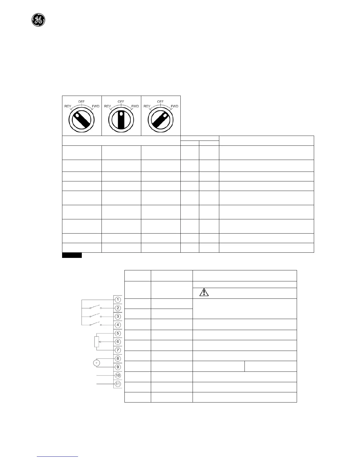
4.7. UsingtheREV/0/FWDSelectorSwitch(SwitchedVersionOnly)
Byadjustingtheparametersettings,theAF-70canbeconfiguredformultipleapplicationsandnotjustforForwardorReverse.
ThiscouldtypicallybeforHand/Off/Autoapplications(alsoknownandLocal/Remote)forHVACandpumpingindustries.
RunReverse STOP RunForward 0 0
FactoryDefaultConfiguration
RunForwardorReversewithspeedcontrolledfromthe
STOP STOP RunForward 0 5,7
RunforwardwithspeedcontrolledformthelocalPOT
RunReverse-disabled
PresetSpeed1 STOP RunForward 0 1
RunForwardwithspeedcontrolledfromtheLocalPOT
PresetSpeed1providesa‘Jog’SpeedsetinH-20
RunReverse STOP RunForward 0 6,8
RunForwardorReversewithspeedcontrolledfromthe
LocalPOT
RuninAuto STOP RuninHand 0 4
RuninHand–SpeedcontrolledfromtheLocalPOT
RuninAuto0SpeedcontrolledusingAnaloginput2e.g.
fromPLCwith4-20mAsignal.
RuninSpeedControl STOP RuninPIControl 5 1
InSpeedControlthespeediscontrolledfromtheLocal
InPIControl,LocalPOTcontrolsPIsetpoint
RuninPresetSpeed
Control
STOP RuninPIControl 5
0,2,4,5,
8..12
InPresetSpeedControl,H-20setsthePresetSpeed
InPIControl,POTcancontrolthePIsetpoint
RuninHand STOP RuninAuto 3 6
Hand–speedcontrolledfromtheLocalPOT
Auto–SpeedReferencefromModbus
RuninHand STOP RuninAuto 3 3
Hand–SpeedreferencefromPresetSpeed1(H-20)
Auto–SpeedReferencefromModbus
TobeabletoadjustparameterH-15,extendedmenuaccessmustbesetinF-14(defaultvalueis101)
4.8. ControlTerminalConnections
1 +24VdcUserOutput
+24Vdcuseroutput,100mA.
Donotconnectanexternalvoltagesourceto
thisterminal.
2 DigitalInput1
Positivelogic
“Logic1”inputvoltagerange:8V…30VDC
“Logic0”inputvoltagerange:0V…4VDC
3 DigitalInput2
4
DigitalInput3/
AnalogInput2
Digital:8to30V
Analog:0to10V,0to20mAor4to20mA
5 +10VUserOutput +10V,10mA,1kΩminimum
6
AnalogInput1/
DigitalInput4
Analog:0to10V,0to20mAor4to20mA
Digital:8to30V
7 0V 0VoltCommon,internallyconnectedtoterminal9
8
AnalogOutput/
DigitalOutput
Analog:0to10V,
Digital:0to24V
20mAmaximum
9 0V 0VoltCommon,internallyconnectedtoterminal7
10 RelayCommon
11 RelayNOContact Contact250Vac,6A/30Vdc,5A

 Loading...


