8. ModbusRTUCommunications
8.1. Introduction
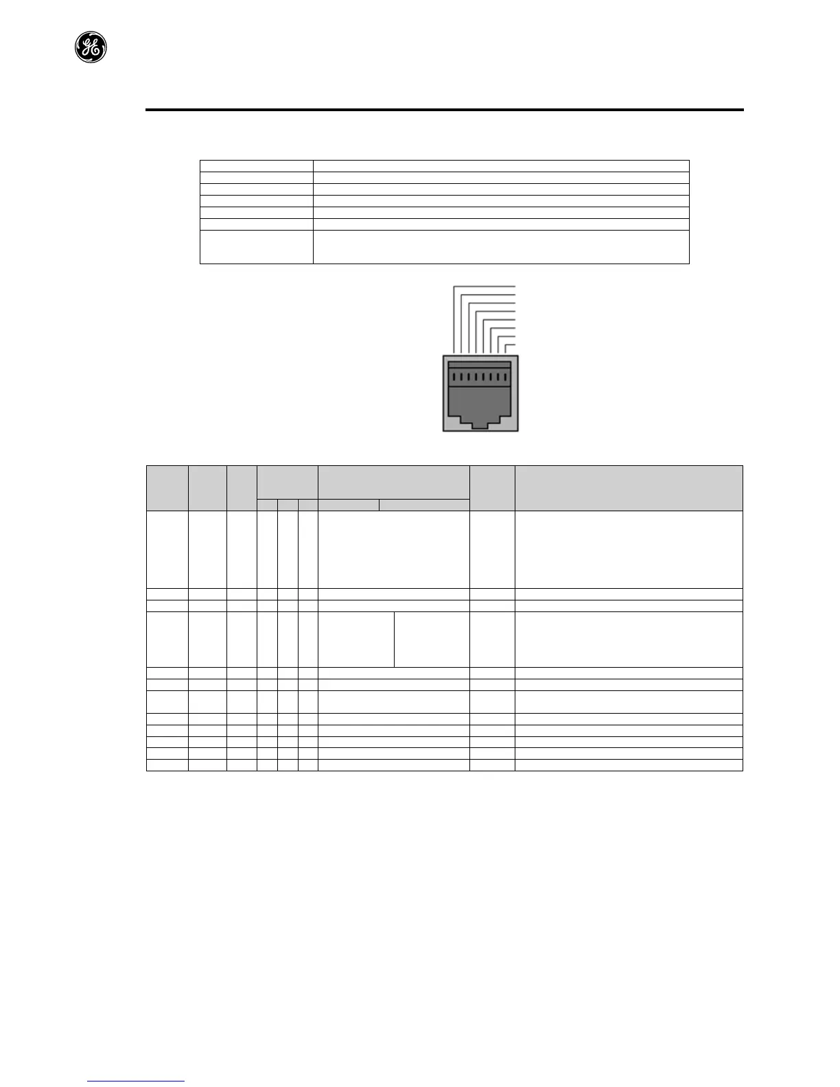
TheAF-70canbeconnectedtoaModbusRTUnetworkviatheRJ45connectoronthefrontofthedrive.
8.2. ModbusRTUSpecification
9600bps,19200bps,38400bps,57600bps,115200bps(default)
1startbit,8databits,1stopbits,noparity.
SupportedFunctionCodes
03ReadMultipleHoldingRegisters
06WriteSingleHoldingRegister
16WriteMultipleHoldingRegisters(Supportedforregisters1–4only)
8.3. RJ45ConnectorConfiguration
ForfullMODBUSRTUregistermap
informationpleaserefertoyourGESales
Partner.Localcontactscanbefoundby
visitingourwebsite
www.geindustrial.com/Drives
WhenusingMODBUScontroltheAnalogand
DigitalInputs
canbeconfiguredasshowninsection7.5
ThisisnotanEthernet
connection.Donotconnect
directlytoanEthernetport.
8.4. ModbusRegisterMap
Register
Number
Function
Range Explanation
Bit0:Low=Stop,High=RunEnable
Bit1:Low=DecelRamp1(F-04),High=Decel
Ramp2(H-24)
Bit2:Low=NoFunction,High=FaultReset
Bit3:Low–NoFunction,High=CoastStop
ModbusSpeedreferencesetpoint
Setpointfrequencyx10,e.g.100=10.0Hz
AccelerationandDecelerationTime
Ramptimeinsecondsx100,e.g.250=2.5seconds
LowByte=DriveErrorCode,seesection10.1
HighByte=DriveStatusasfollows:-
0:DriveStopped
1:DriveRunning
OutputfrequencyinHzx10,e.g.100=10.0Hz
OutputMotorCurrentinAmpsx10,e.g.10=1.0Amps
Indicatesthestatusofthe4digitalinputs
LowestBit=1Input1
Analoginput%offullscalex10,e.g.1000=100%
Analoginput%offullscalex10,e.g.1000=100%
Displaysthesetpointfrequencyx10,e.g.100=10.0Hz
DriveheatsinktemperatureinºC
AlluserconfigurableparametersareaccessibleasHoldingRegisters,andcanbeReadfromorWrittentousingtheappropriateModbus
command.TheRegisternumberforeachparameterF-04toH-60isdefinedas128+Parameternumber,e.g.forparameterH-15,theregister
numberis128+15=143.Internalscalingisusedonsomeparameters,forfurtherdetailspleasecontactyourGESalesPartner.

 Loading...


