GE MEDICAL SYSTEMS CT 9800 QUICK SYSTEM
Rev. 12 Direction 18000
6-9-2
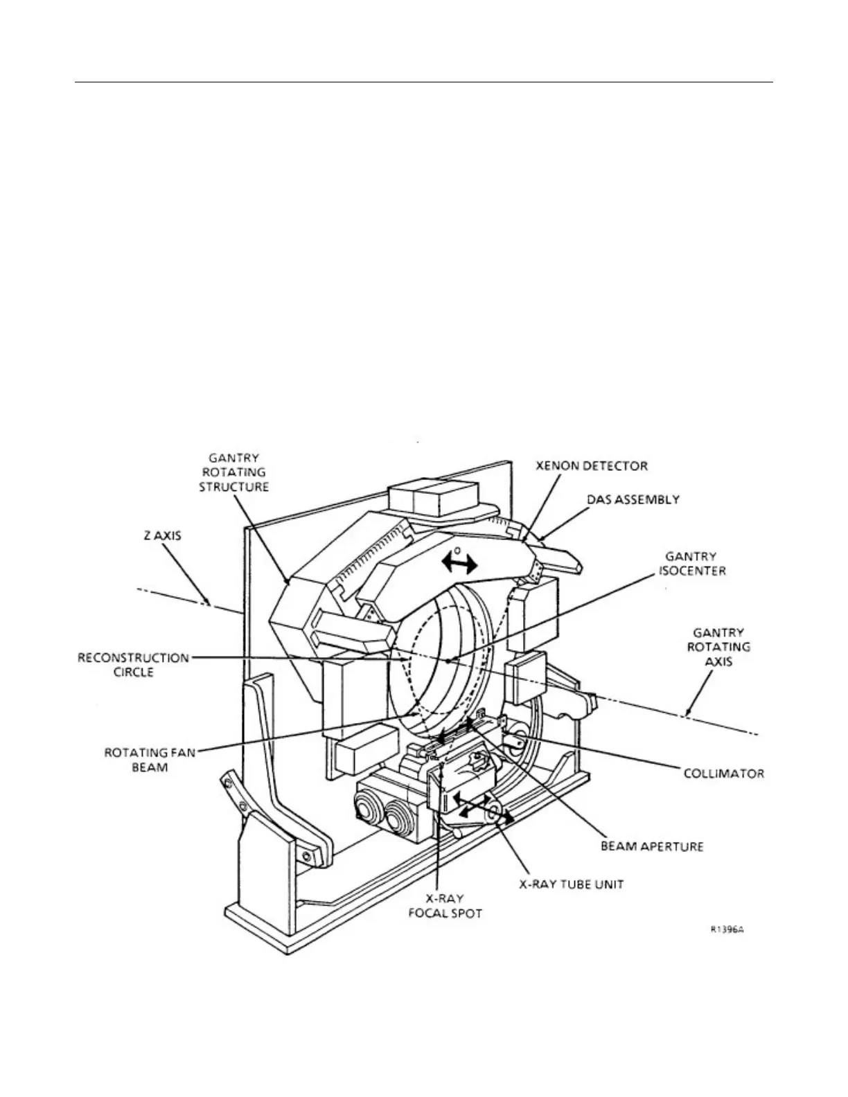
Directions in the gantry geometry are defined as follows:
• Theta- Along the tangent to gantry rotation; i.e., clockwise (+) or counter clockwise (-) on the rotating
structure. 0° theta is defined with the tube unit at bottom dead center.
• Z Axis- Parallel to the axis of gantry rotation; i.e., towards or away from the patient table, or in the
direction of cradle motion. + is toward the table, - is away from the table.
• Radial Along the radius from the center of gantry rotation; i.e., in and out from the gantry isocenter.
NOTE: There is no radial adjustment of the tube, collimator, or detector. This dimension is fixed by design.
The tube unit is adjustable in the theta and the Z dimensions.
The collimator is adjustable only in the theta dimension.
The detector is only adjustable in the Z dimension.
4. Illustration 6-9-2 is a schematic of the gantry components at 0° theta when viewed from the table and the
right side of the gantry. The fan beam is nominally 2.16” off the collimator mounting surface and 1.805” off
the detector mounting surface.
ILLUSTRATION 6-9-1
 Loading...


