GE MEDICAL SYSTEMS CT 9800 QUICK SYSTEM
Rev. 12 Direction 18000
6-9A-11
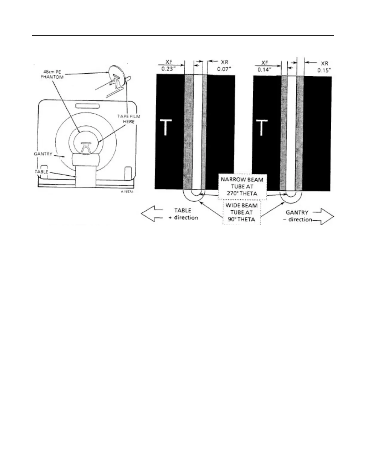
ILLUSTRATION 6-9A-9 ILLUSTRATION 6-9A-10A ILLUSTRATION 6-9A-10B
BAD P.O.R. GOOD P.O.R.
5. Remove and develop the film. Mark a “T” on the film to identify the table side as in Illustration 6-9A-10.
Verify that the narrow exposure lies within the wider X-Ray exposure.
Examine the edges of the two exposures in the Z direction. Both edges of each beam should be equally well
defined with the edges of the narrow beam much sharper that the wide beam. If there is a difference in edge
definition, check for gross Z misalignment where the slit in the tube collimator adapter is defining the fuzzy
edge. Both edges of the beam should be defined only by the exit slit of the collimator.
6. Measure the 10 mm exposure to determine the plane of rotation. Use a Pocket Comparator with reticle or
vernier caliper to measure the two widths of the wide beam not covered by the narrow beam. If these
dimensions are XF(front) and XR(rear), then the difference in centers of the two beams is [XF-XR]/2.
To meet the “cold” tube conditions and maintain the perpendicularity specification of the fan beam, [XF-XR]/2
must fall in the range of 0.0 to -0.010” (-0.25mm).
That is, XF must be equal or slightly less than XR as follows:
XF = XR (+0.0, -0.02) or XF = XR (+0.0mm, -0.5mm)
7. If the 10mm beam XF and XR measurements do not meet the specification in Step 6, shift the Z position of
X-Ray tube toward the wider of the two beams. By gantry geometry, the tube shift should be .26 times the
difference between XF and (XF - 0.02”).
Tube Shift = 0.26 [XF - XR + 0.02”] = 0.26 [XF - XR + 0.5mm]
 Loading...


