GE MEDICAL SYSTEMS CT 9800 QUICK SYSTEM
Rev. 9 Direction 18000
4-3-8
3-1 Power Checks (Continued)
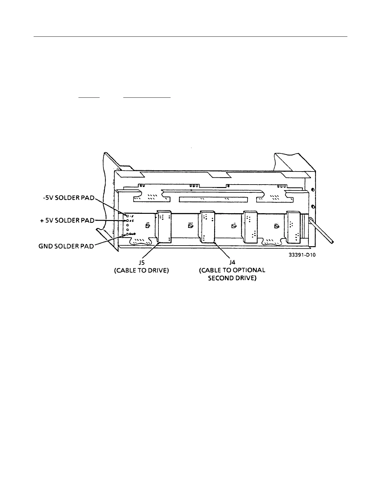
h. Measure the +5V and -5V power supplies at the solder pads on the back of the disk adapter as shown in
Illustration 4-3-6. The limits are:
Voltage Acceptable Level
+ 5V 4.90 to 5.10V
- 5V -4.90 to -5.10V
If out of spec, adjust the Power Supplies per the procedure in Chapter 6 (Adjustments) of this manual.
ILLUSTRATION 4-3-6
DISK ADAPTER BACKPLANE
(Viewed from rear of cabinet )
5. Argus Disk Unit
Note: If an Argus Disk drive is not present in your system, proceed to step 6.
a. Ensure the Front Panel switch is in the OFF position. Refer to Illustration 4-3-7.
b. Locate Argus Cabinet and Argus Chassis AC Circuit Breakers and ensure they are OFF. Refer to
Illustration 4-3-8.
c. For initial installation of Argus Disk Drive, verify Voltage Jumper and Frequency Stunt Plugs
configuration on the Power Supply Assembly in the rear of the Drive. Refer to Illustration 4-3-9.
d. Turn ON Argus front panel switch. Check “ON-1” LED on Argus front panel, it should be ON.
 Loading...


