GE Energy
D20/D200
Installation and Operations Guide
General 994-0078-2.00-7
Full
41
Familiarization, continued
RS-232 Switch
Panel:
Connectors
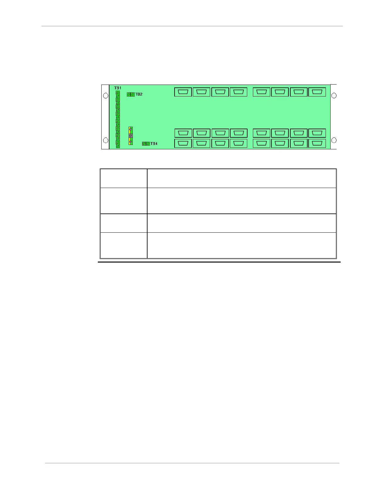
RS-232 Switch Panel connectors, accessible from the rear of the panel, are illustrated
below:
TB 3
J1
J8
P9
P16
P1
P8
P10
P13
P12P11 P14 P15
P7P6P5P4P3P2
J2 J3 J4 J5
J6
J7
The connectors have the following functionality:
P1 through P16 Provide serial connections to each of the two CCUs. P1 through P8 are
connected to CCU A, and P9 through P16 are connected to CCU B.
J1 through J8 Connect to field equipment. If CCU A is active, serial connections P1
through P8 are switched to J1 through J8. If CCU B is active, serial
connections P9 through P16 are switched to J1 through J8.
TB1 Connect the monitor and control cables (referred to as the Watchdog
cables) from each of the CCUs.
TB2, TB4 In systems with more than eight serial port connections, TB2 and TB4
are used to interconnect multiple RS-232 Switch Panels. A maximum of
eight RS-232 Switch Panels can be cascaded.