D20/D200
Installation and Operations Guide
GE Energy
994-0078-2.00-7 General
76
Full
Connections and Configuration, continued
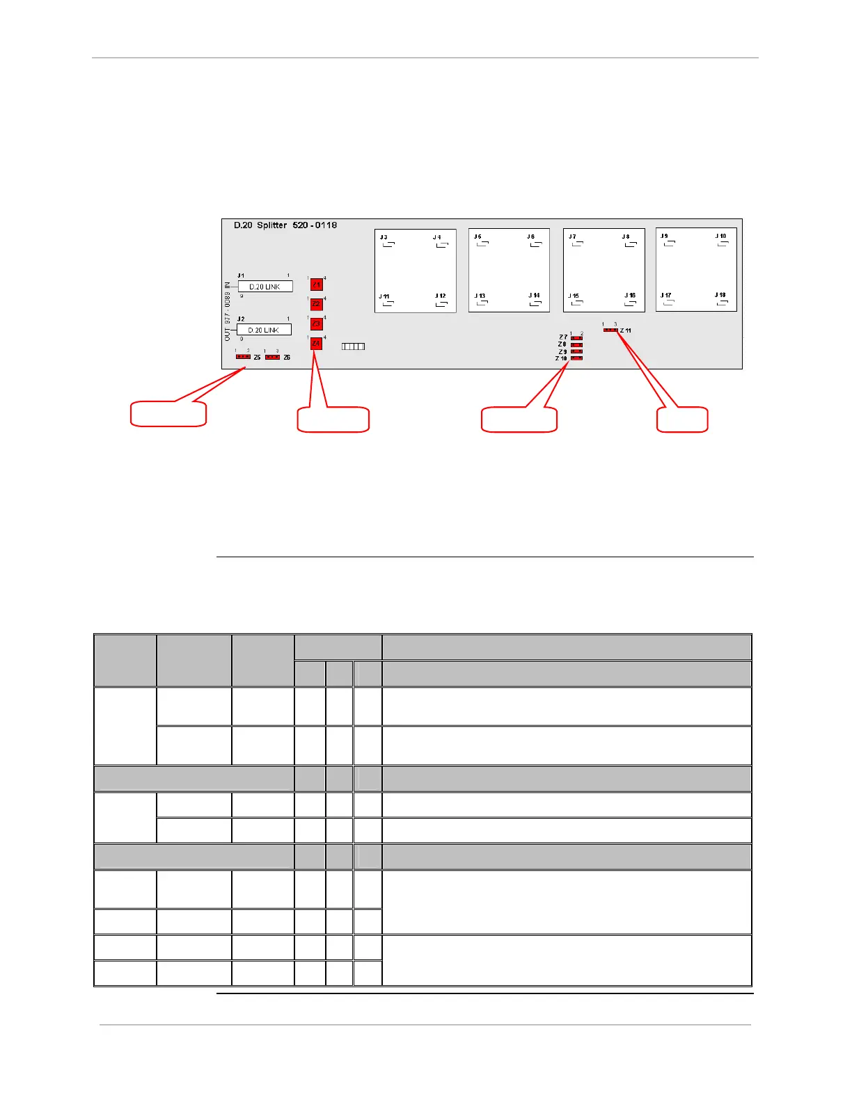
D.20 Splitter:
Jumpers
Jumper locations on the D.20 Splitter:
Use jumpers:
• Z1 to Z4 for external power setting
• Z5 and Z6 for D.20 channel used
• Z7 to Z11 for SW base compatibility setting
D.20 Splitter:
Settings
The following table gives jumper settings for Z1 to Z11.
Option 1 Jumper Definition – External Power Jumper
Number
Jumper
Position
Jumper
Setting
1A 1B 1C
1 – 4 & 2 –
3
OUT
√
D.20 Link Power Supplies Splitter Z1 to Z4
1 – 4 & 2 –
3
IN
√
External Power on TB1 supplies D.20 Link and Splitter
2A 2B
Jumper Definition – D.20 Channel Used
1 – 2 IN
√
D.20 Channel 1 Used Z5 to Z6
2 – 3 IN
√
D.20 Channel 2 Used
3A 3B
Jumper Definition – S/W Base Compatibility
Z7 to Z10 1 – 2 ALL
OUT
√
Z11 2 – 3 IN
√
ALL OTHER BASES (DEFAULT)
Z7 to Z10 1 – 2 ALL IN
√
Z11 2 – 3 IN
√
Base 3.11, Pre-Win or Older
Z5 & Z6
Z1 to Z4 Z7 to Z10 Z11