GE Grid Solutions
GE Information 994-0081-3.00-21
Chapter 5: Operating the D25
LED Indicators
Front Panel
Indicators
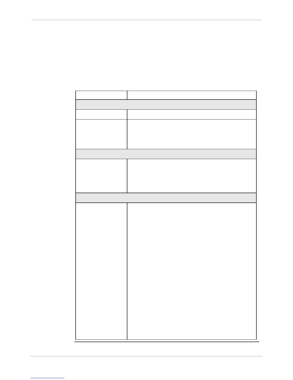
The front panel has three sets of LED indicators, providing a visual indication
of the operational status of the unit:
LED Color and Function
OPERATION
POWER
Green: on when power supply is operating normally.
RUN
Green: on when the D25 microprocessor system is
running. With a Type III WESDAC board the RUN
LED flashes at about 2 Hz, depending on processor
load.
COMMUNICATIONS
IED1 (COM 3)
IED2 (COM 4)
XCOM 1 (COM 5)
XCOM 2 (COM 6)
Red: on to indicate whether and when each port is
transmitting (TX) and/or receiving (RX):
Note: XCOM indicators light only if card is
installed.
CONTROLS
LOCAL
REMOTE
The D25 Plant I/O Subsystem monitors the state of
the CONTROLS switch only if a control board is
installed.
If the CONTROLS switch is in the REMOTE
position at startup:
• green LOCAL LED lights immediately when the D25
is turned on.
• green LED remains on until the D25’s internal POST
diagnostics are complete.
• if the diagnostics do not pass, the indicator remains
green.
After the D25 has started up normally, the indicator
should follow the state of the CONTROLS switch:
• if the switch is moved to the REMOTE position, the
red REMOTE LED lights after a momentary delay,
and the LOCAL LED turns off.
Local/Remote LEDs flashing indicate one or more active
sealed-in outputs (only if a D25 High Current KE Control
Output Module is present in the D25)