GE Grid Solutions
994-0081-3.00-21 GE Information
Configuring Radio Keying Option
Configuring
Radio Keying
Option
The IED/RTC board (Revision 7) includes a configuration jumper that can be
used to enable or disable the Serial XCOM Radio Keying option.
Procedure:
Option Change
Steps to access and change the JP1 option jumper on IED/RTC module:
Step Action
1 Remove the shelf plate as described in the procedure on page 124.
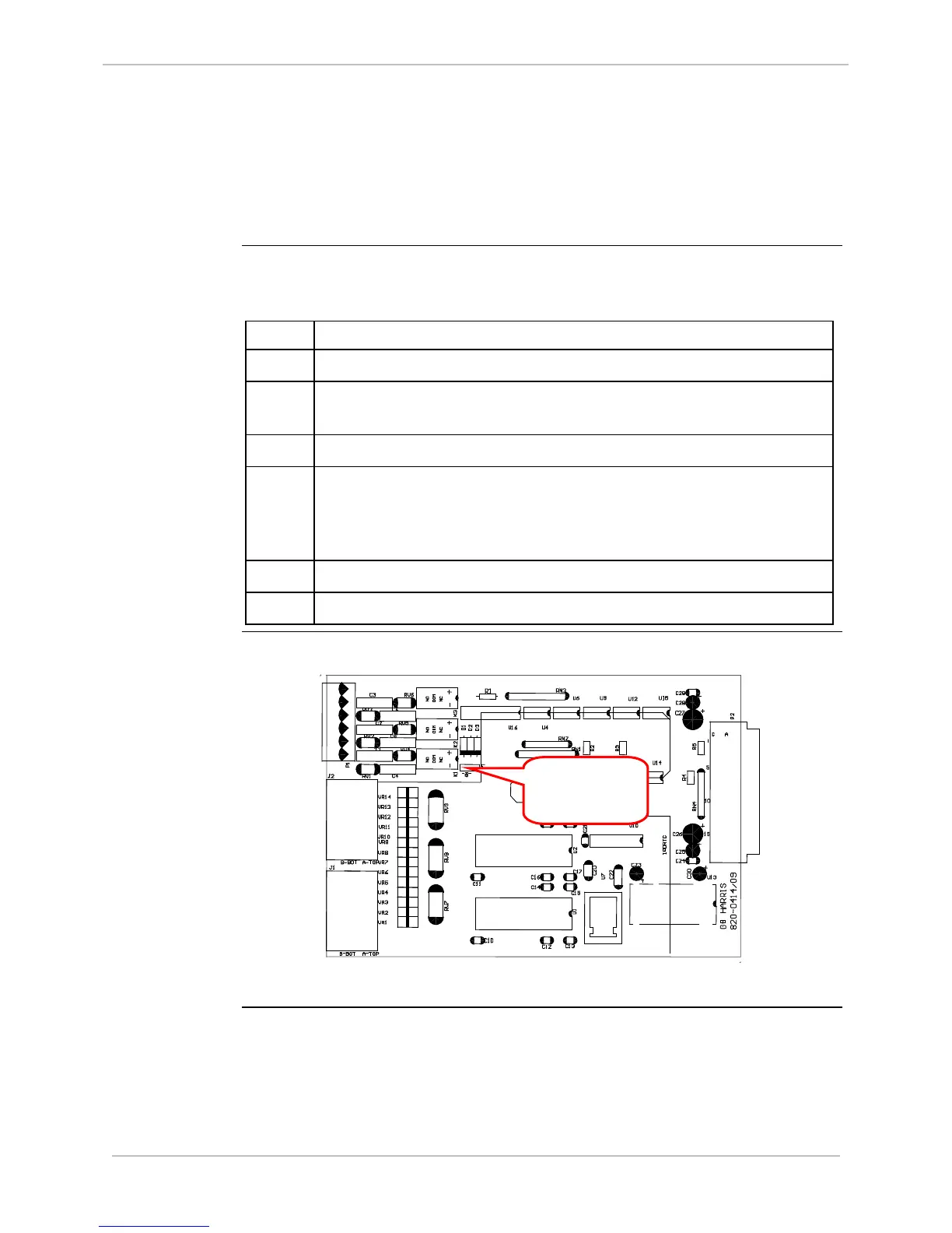
2 Locate the jumper JP1 on the IED/RTC module you are using,
referring to the following diagram.
3 Remove the JP1 jumper by pulling it straight up from its pins.
4 Reposition the jumper over the desired pins.
Jumper JP1 pins 1 – 2 to enable radio keying
Jumper JP1 pins 2 – 3 to disable radio keying
5 Push the jumper straight down onto the two pins
6 Replace the shelf plate into the D25 enclosure.
IED/RTC Card
Layout
Diagram
Keying