GE Grid Solutions
GE Information 994-0081-3.00-21
Connecting DNP3 I/O Modules (Low Voltage)
For a Low Voltage (LV) DNP3 I/O module, connect the:
• Interconnect cabling between each DNP3 I/O module, and
• Power to the last DNP3 I/O module of the chain.
DNP3 I/O Module (LV) Interconnect Cabling
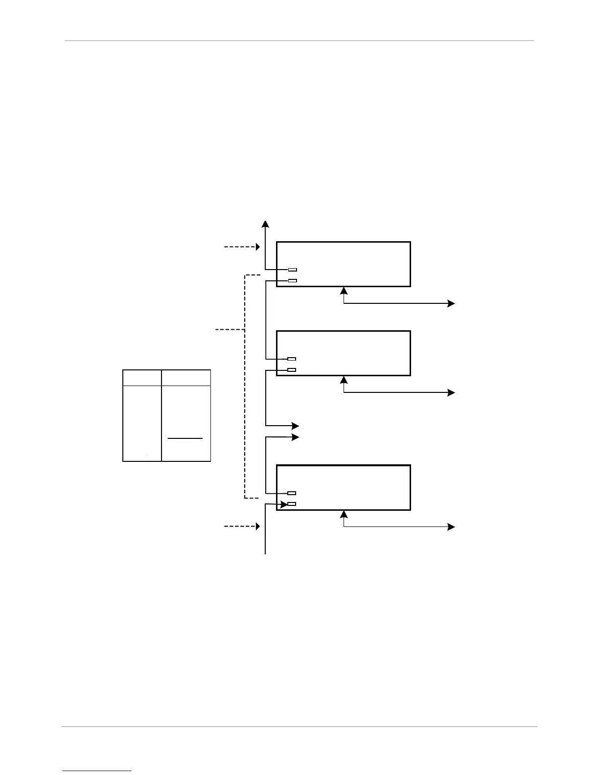
The DNP3 I/O module interconnect cabling is shown below:
First DNP I
/
O
Module
Second DNP I/
O
Module
J
1
To Field Equipment
To Field Equipment
J1
J2
J2
Daisy-
chained
to other DNP I
/O
Modules
Last DNP I/O
Module
To Field Equipment
J1
J2
Pin
1
4
5
6
7
Other
Function
GND
+
DC1
-DC1
TX/
RX2
TX/RX2
Not Used
To RTU Master
To Power Source
RTU Master
Cable
GE Part
Number
IP
- Server
977-
0503
J1
J2
Cable: D25 (RTU Master
)
GE Part Number:
977-0502
To D25 (RTU Master)
To Field Equipment
To Field Equipment
To Field Equipment
To Power Source
J1
J2
J1
J2
J1
J2
Cable:
Power Source
GE Part Number: 997-0500
Standard Cables DB9
male to DB
9 male
GE part number:
977
-0089
After DNP3 I/O modules have been interconnected, you are now ready to connect power to the DNP3 I/O
modules. See the following subsection: DNP3 I/O module (LV) connection to the Power Source.
DNP3 I/O Module (LV) Connection to the Power Source
Connect the power supply to the last DNP3 I/O module in the chain.
The cable from J2 on the last DNP3 I/O module to the power source (GE part number 977-0500) provides
the connections shown in the following wiring diagram.