GE Grid Solutions
994-0081-3.00-21 GE Information
Power Supply Card, Continued
Procedure:
Output Voltage
Change
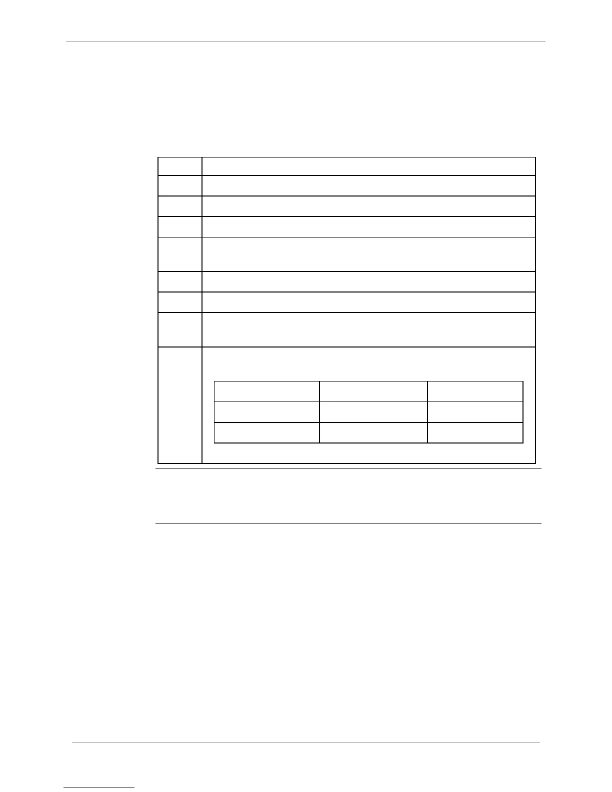
Steps to change the field output voltage on any of the four power supplies:
Step Action
1 Remove the shelf plate as described in the procedure on page 124.
2 Locate the jumper P3, as shown in the above diagram.
3 Remove the jumper by pulling it straight up from its pins.
4 Position the jumper over the P3 center pin and pin labeled 24V or
48V, as desired.
5 Push the jumper straight down onto the two pins
6 Replace the shelf plate into the D25 enclosure.
7 Remove the fuse F1 from its holder at the rear of the D25
enclosure
8 Replace the fuse with one of the correct value, as seen in this list:
Output Voltage Fuse Type Part #
24
V
dc
AGC 1.0A 250V 940-0021
48 V
dc
MDL 0.5A 250V 940-0215
Note
Changing the position of P3 changes the part number of the power supply.
Be sure to record and/or label the power supply, identifying the change from
the default settings.