GE Grid Solutions
994-0081-3.00-21 GE Information
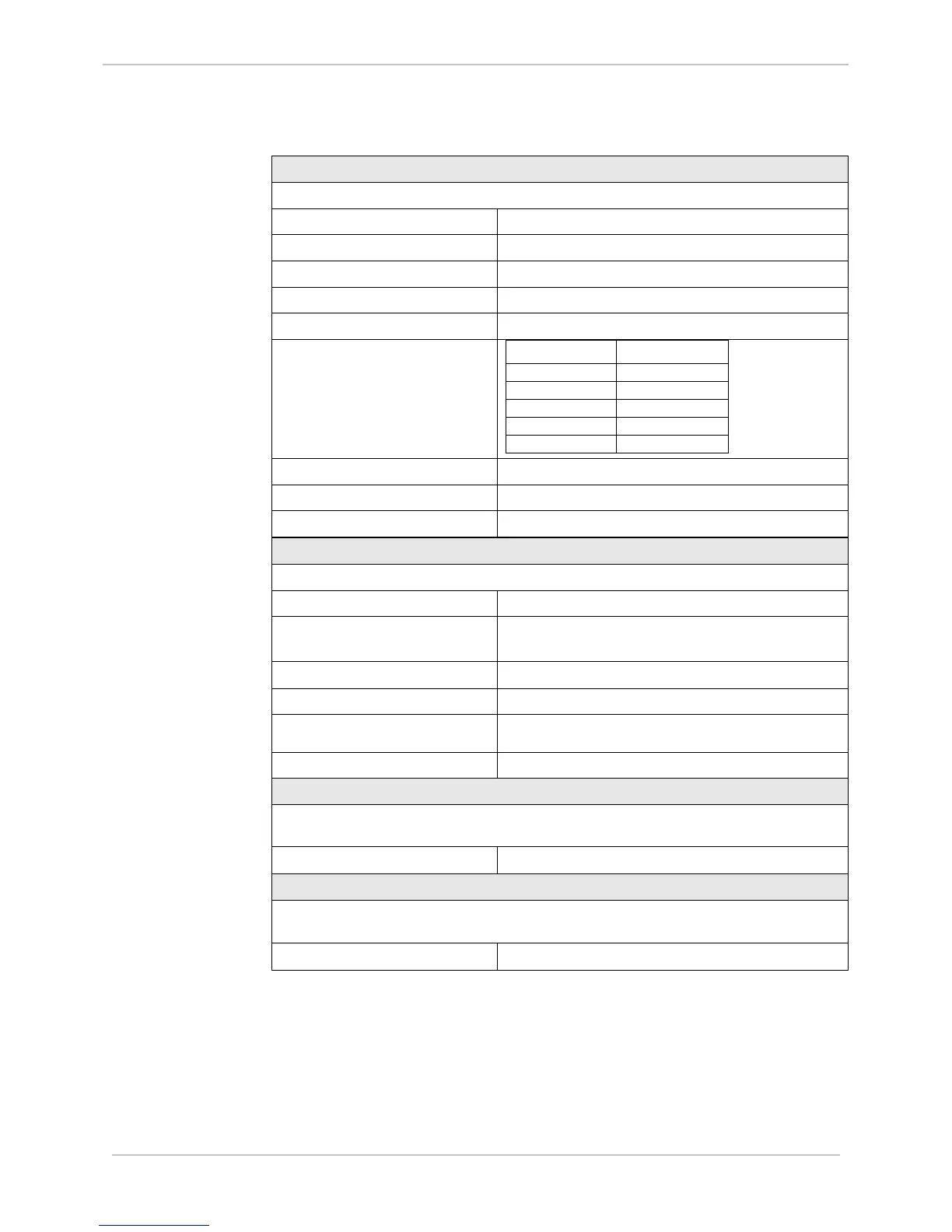
Electrical Specifications, Continued
Auxiliary Digital Outputs
Three single digital outputs for System Fail indication, Radio Keying and Auxiliary Digital output
System Fail Relay Contacts 1 Form B (Normally Closed) Relay
Radio keying, and auxiliary relay 1 Form A (Normally Open) Relay
Maximum Switching Voltage 220 V
dc
Minimum Switching Voltage 10 μA, 10 mV
dc
Carry Continuous 2.00 A
Break (DC resistive)
Voltage Current
Operate time < 4 ms
Max switching speed 20 changes/sec at rated break load
Contact material Silver (Ag) with Gold (Au) flash
DC Analog Inputs
16 optically isolated differential inputs
Measurement Range 120% of nominal
Overload Voltage
±30 V
dc
(NM) continuous
±200 V
dc
(CM) continuous
Nominal Voltage Input Range
±5 V
dc
Voltage Input Impedance Greater than 10 MΩ
Nominal Current Input Range
±1 mA, ±5 mA, ±10 mA, or ±20 mA
Current Input Burden 5k to 250Ω (1 to 20 mA)
AC Analog Measurement
Direct AC analog inputs from CTs and PTs. One to six 3-phase circuits. 15 AC analog inputs
organized in groups of three (3) inputs, transformer isolated
Line Frequency
50/60 Hz, nominal ±5 Hz
AC Analog Measurement
Direct AC analog inputs from CTs and PTs. One to six 3-phase circuits. 15 AC analog inputs
organized in groups of three (3) inputs, transformer isolated
Line Frequency
50/60 Hz, nominal ±5 Hz