GE Grid Solutions
994-0081-3.00-21 GE Information
Control Outputs, Continued
D25KE DB-25
Combined R/L
and T/C
Trip/Close and Raise/Lower digital outputs can be used on the same D25KE
DB-25 module.
Note
The three examples shown below are the only recommended configuration
options for combining trip/close and raise/lower in one D25KE.
Do Not configure raise/lower points with point numbers lower than the
trip/close point numbers as it may result in wiring problems, and interposing
relay connection problems.
Combined T/C
and R/L
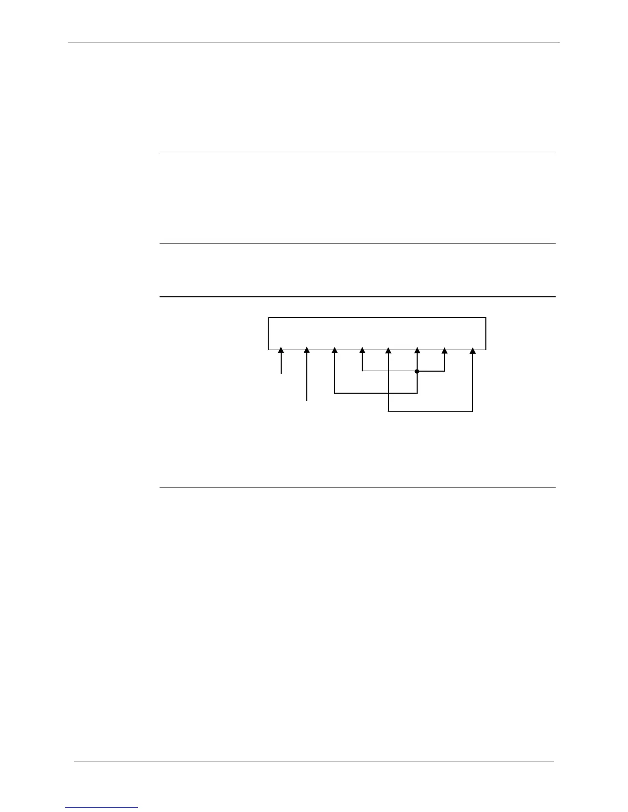
Example #1
In the following example, the first 24 digital outputs are configured as
trip/close, and the last 8 are configured as 4 raise/lower pairs.
P1 connections
for Combined
Raise/Lower
and Trip/Close
T/C 9 - 16
T/C 1 - 8
Control
Control
Voltage
Return
R/L 4 - 1
T/C 17 - 24