GE Grid Solutions
994-0081-3.00-21 GE Information
Testing Hardware I/O Points, Continued
Note
Only points used by the Plant I/O, based on downloaded configuration, will
display values.
Unused points will be off-line.
Table:
Reference
Values
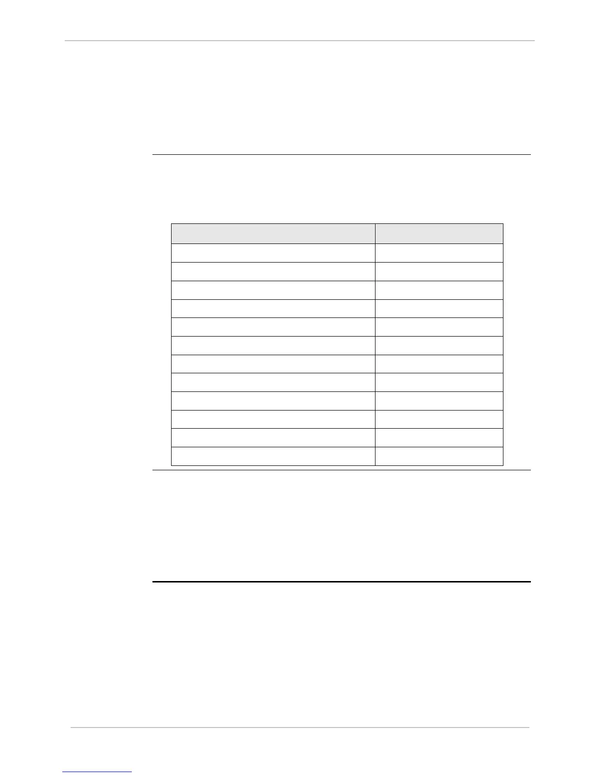
Use this table as example references for the AC analog input verification test.
Note: Nominal values can be determined by reviewing SGConfig’s P097
Plant I/O configuration tables for this device.
Point Description Nominal Value
Voltage Phase A Circuit 1 13107
Voltage Phase B Circuit 1 13107
Voltage Phase C Circuit 1 13107
Current Phase A Circuit 1 2048
Current Phase B Circuit 1 2048
Current Phase C Circuit 1 2048
Neutral Current Circuit 1 2048
Voltage Phase A-B Circuit 2 13107
Voltage Phase B-C Circuit 2 13107
Current Phase A-B Circuit 2 2048
Current Phase B-C Circuit 2 2048
Neutral Current Circuit 2 2048
Notes
• Full-scale for all AC analog values displayed in WESMAINT is represented by a
count of 32767 (15-bit plus sign value).
• Full-scale of voltage measurements is 2.5 times the nominal value.
• Full-scale of current measurements is 16 times the nominal value.
• For more detailed information, refer to the D25 Plant I/O Subsystem
Configuration Guide.