EasyManua.ls Logo

GE D30 User Manual

GE D30
686 pages
To Next Page IconTo Next Page
To Previous Page IconTo Previous Page
Page #102 background imageLoading...
Page #102 background image
3-50 D30 LINE DISTANCE PROTECTION SYSTEM – INSTRUCTION MANUAL
DIRECT INPUT AND OUTPUT COMMUNICATIONS CHAPTER 3: INSTALLATION
3
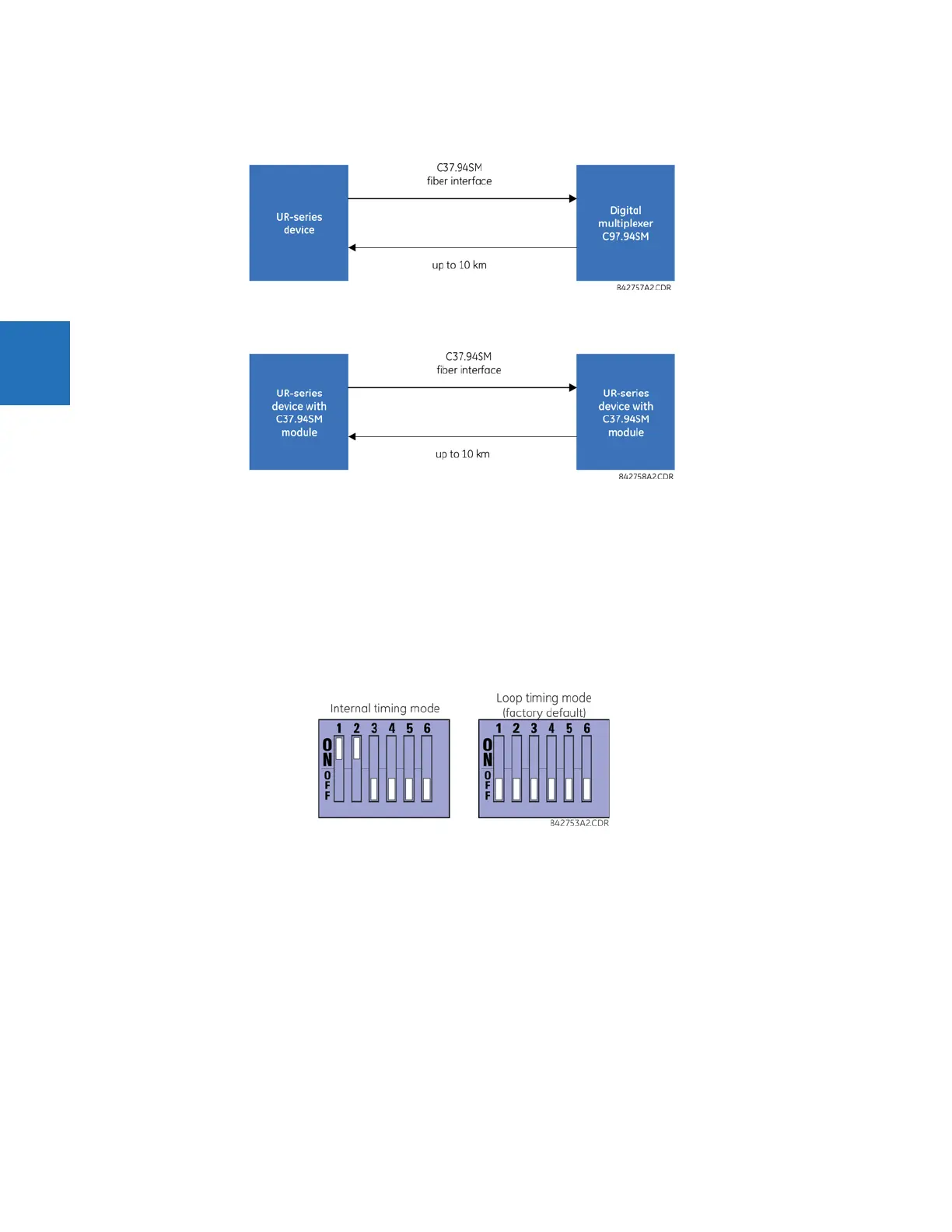
The UR-series C37.94SM communication module can be connected directly to any compliant digital multiplexer that
supports C37.94SM, as shown.
It also can be connected directly to any other UR-series relay with a C37.94SM module, as shown.
In 2008, GE Grid Solutions released revised modules 2A and 2B for C37.94SM communication to enable multi-ended fault
location functionality with firmware 5.60 release and higher. All modules 2A and 2B shipped since the change support this
feature and are fully backward compatible with firmware releases below 5.60. For customers using firmware release 5.60
and higher, the module can be identified with "Rev D" printed on it and is to be used on all ends of D30 communication for
two and three terminal applications. Failure to use it at all ends results in intermittent communication alarms. For
customers using firmware revisions below 5.60, it is not required to match the revision of the modules installed.
The UR-series C37.94SM module has six switches that are used to set the clock configuration. The following figure shows
the functions of these control switches.
Figure 3-58: Switches
For the internal timing mode, the system clock is generated internally. Therefore, set the timing switch selection to internal
timing for relay 1 and loop timed for relay 2. There must be only one timing source configured.
For the looped timing mode, the system clock is derived from the received line signal. Therefore, set the timing selection to
loop timing mode for connections to higher-order systems.
The C37.94SM communications module cover removal procedure is as follows:
1. With power to the relay off, remove the C37.94SM module (module 2A or 2B) as follows. Record the original location of
the module to help ensure that the same or replacement module is inserted into the correct slot.
2. Simultaneously pull the ejector/inserter clips located at the top and at the bottom of each module in order to release
the module for removal.
3. Remove the module cover screw.
4. Remove the top cover by sliding it towards the rear and then lift it upwards.
5. Set the timing selection switches (channels 1 and 2) to the required timing modes (see description earlier).

Table of Contents

Question and Answer IconNeed help?

Do you have a question about the GE D30 and is the answer not in the manual?

GE D30 Specifications

General IconGeneral
BrandGE
ModelD30
CategoryRelays
LanguageEnglish

Summary

Chapter 1: Introduction

1.1 Safety symbols and definitions

Explains safety and equipment symbols used in the manual to prevent injury, damage, or downtime.

Chapter 2: Product description

2.1 Product description

Describes the D30 Line Distance Protection System, its functions, and features.

2.2 Security

Details the security features available, including password protection and CyberSentry.

2.5 Specifications

Lists the technical specifications for various protection elements, including phase and ground distance.

2.5.1 Protection elements

Details specifications for protection elements like phase distance, directionality, and reach accuracy.

2.5.8 Communication protocols

Lists supported communication protocols like IEC 61850, RS232, USB, and RS485.

2.5.10 CyberSentry security

Outlines options for CyberSentry security configuration.

Chapter 3: Installation

3.1 Unpack and inspect

Details the procedure for unpacking and inspecting the relay, checking delivered items, and inspecting for damage.

3.3 Wiring

Provides information on wiring the relay, including typical diagrams and module connections.

3.5 Activate relay

Explains how to activate the relay using the front panel or EnerVista software.

3.6 Install software

Provides instructions for installing EnerVista UR Setup software.

3.7 Add device to software

Guides on adding devices to the EnerVista software for configuration and monitoring.

3.7.1 Set IP address in UR

Details how to set the IP and subnet addresses for Ethernet communication in the UR.

3.7.2 Configure serial connection

Explains how to configure serial connections for local (front RS232) and remote (rear RS485) access.

3.7.3 Configure Ethernet connection

Guides on connecting the Ethernet cable and configuring the device for Ethernet communication.

3.8 Connect to the D30

Details the four methods for connecting to the D30 device: RS232/USB, RS485, Ethernet, and LAN.

3.9 Set up CyberSentry and change default password

Guides on setting up CyberSentry security and changing the default password.

Chapter 4: Interfaces

4.1 EnerVista software interface

Explains the EnerVista UR Setup software's role in configuring, monitoring, and troubleshooting relays.

4.1.1 Introduction

Explains the EnerVista UR Setup software's role in configuring, monitoring, and troubleshooting relays.

4.1.8 Secure and lock FlexLogic equations

Explains how to secure FlexLogic equations to prevent unauthorized viewing or modification.

4.1.9 Settings file traceability

Explains the traceability feature for settings files to track changes and security.

4.2 Front panel interface

Explains the use of enhanced, standard, and graphical front panels.

4.2.1 Front panel

Describes the components of the front panel: enhanced, standard, and graphical.

4.2.9 Breaker control

Explains breaker control operations, including mode selection, front panel control, and control of two breakers.

Chapter 5: Settings

5.1 Settings menu

Outlines the structure of the settings menu, including product setup, security, and communications.

5.3 Product setup

Details product setup options including security, display properties, and communication protocols.

5.3.1 Security

Explains security features like password, EnerVista, and CyberSentry security, including lost password recovery.

5.3.3 Graphical front panel

Describes configuration of the graphical front panel, including home page, rolling mode, and metering editor.

5.3.5 Communications

Outlines communication settings including serial ports, network, protocols, and specific protocol configurations.

5.3.6 Grouped elements

Explains grouped elements and their settings, including line pickup, distance, ground distance, and power swing.

5.8 Control elements

Covers control elements such as trip bus, setting groups, selector switch, and autoreclose.

5.9 Inputs/outputs

Details configuration of contact inputs, virtual inputs, contact outputs, virtual outputs, and resetting.

5.11 Testing

Provides information on testing the relay's functionality, including test modes and forcing functions.

Chapter 6: Actual values

6.1 Actual values menu

Outlines viewing actual values from the front panel and EnerVista software.

6.3 Status

Displays the present status of contact inputs, virtual inputs, RxGOOSE elements, and communication status.

6.4 Metering

Details metering values for sources, phase current, ground current, phase voltage, auxiliary voltage, power, frequency.

6.5 Records

Describes how to view fault reports, event records, oscillography, data logger, and breaker maintenance records.

Chapter 7: Commands and targets

7.1 Commands menu

Outlines relay directives for operations personnel, including virtual inputs, clear records, and security.

7.2.2 Relay self-tests

Details major and minor self-test errors, their descriptions, and troubleshooting steps.

Chapter 8: Application of settings

8.1 Application guidelines

Provides general application guidelines for stepped distance, overcurrent, and pilot protection.

8.2 Distance elements (stepped distance scheme)

Explains phase and ground distance elements, including supervision, zones, and characteristics.

Chapter 9: Theory of operation

9.1 Distance elements

Explains distance elements, memory voltage polarization, and supervising functions.

9.3 Ground directional overcurrent

Explains ground directional overcurrent elements and their operation with negative-sequence current.

Chapter 10: Maintenance

10.1 Monitoring

Outlines methods for monitoring devices and data, including site targets and Modbus analyzer.

10.7 Back up and restore settings

Provides procedures for backing up and restoring settings to ensure data integrity.

Appendix B: RADIUS server configuration

B.1 RADIUS server configuration

Provides an example procedure for setting up a simple RADIUS server using FreeRADIUS software.

Related product manuals