CHAPTER 4: INTERFACES FLEXLOGIC DESIGN USING ENGINEER
D30 LINE DISTANCE PROTECTION SYSTEM – INSTRUCTION MANUAL 4-67
4
4. Optionally right-click the new tab and Rename it.
5. Add the input blocks to the logic diagram. For example, click the I/O Tokens tab on the right, click the Input element,
then click in the logic sheet to add it. Or drag-and-drop it.
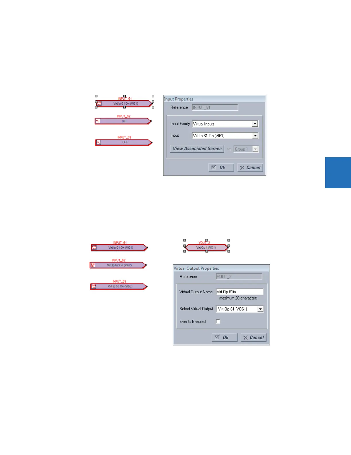
6. Double-click the block on the sheet to configure it, selecting from the two drop-down lists. The figure shows that
virtual input 61 is being added. The View Associated Screen button opens its settings window.
Figure 4-71: Configuring an input block
7. Add the output blocks to the logic diagram. For example, click the I/O Tokens tab, click the Virtual Output element,
then click in the logic sheet to add it. Double-click the block on the sheet to configure it. For the name, make it unique.
The figure shows virtual output 61 is being added, with a suffix of "io" added to the name to make it unique. Note that
the outline color of a block is red until it is configured, and that this properties window varies by block and the
selectable options by order code.
Figure 4-72: Configuring an output block
8. Connect the input blocks to the output blocks by drawing a line as follows. Click the Drawing Tools tab, then select the
Line option. The cursor needs to be at the connection point to end the line, not elsewhere on the block. Note that the
outline color is no longer red on the blocks.