4-70 D30 LINE DISTANCE PROTECTION SYSTEM – INSTRUCTION MANUAL
FLEXLOGIC DESIGN USING ENGINEER CHAPTER 4: INTERFACES
4
The location of these files is C:\ProgramData\GE Power Management\urpc, for example, in the Offline and Online folders.
Any FlexLogic equations entered in the Offline Window area are erased. The logic drawn in the Logic Designer window in
Engineer in the Offline Window area remain. The warning icon disappears after updating.
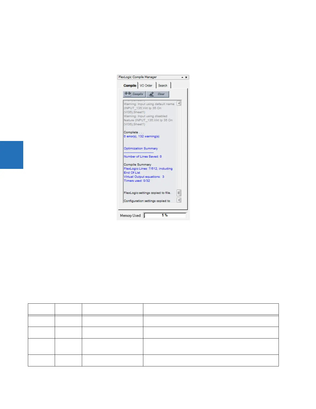
The following information is contained in the compile window.
Figure 4-79: Compiled results
Number of Lines Saved — The number of compiled logic lines eliminated by using the optimization algorithm, as set in the
Optimize Compiled Output option of the Preferences. In the example shown, no lines were saved because the optimizer is
disabled.
FlexLogic Lines — The number of lines that the compiled logic uses, for example seven of 512 available.
Virtual Output equations — The number of FlexLogic equations used in the Logic Designer window.
Timers used — The number of timers used in the Logic Designer window.
Memory Used — The percent of memory used in the Logic Designer window.
Errors
Table 4-3: Errors from compiling
Category Block or gate
affected
Message Description
Error All Number of lines (nnn) exceeds
maximum limit of 512
The compiled result exceeds the limit of 512. Reduce the number of
equations to 512 or less.
Error Tag-In Tag-in not configured (TAG_ID,
SheetReference)
A Tag-In is connected to a circuit but the Tag-In is not referencing an
existing Tag-Out
Error 1 Shots One Shot is over limit
(SYMBOL_ID, SheetReference)
The number of One-Shots contained within all of the VO blocks has
exceeded the maximum allowed for the firmware revision. This value can
either be 0 or 32.
Error =VO VO has no inputs (VO_ID,
SheetReference)
A Virtual Output block is located within the FlexLogic diagram and there
is no block connected as input to it. Connect and identify the inputs.