CHAPTER 5: SETTINGS FLEXLOGIC
D30 LINE DISTANCE PROTECTION SYSTEM – INSTRUCTION MANUAL 5-181
5
[97] OR(3)
[98] TIMER 2
[99] = Virt Op 4
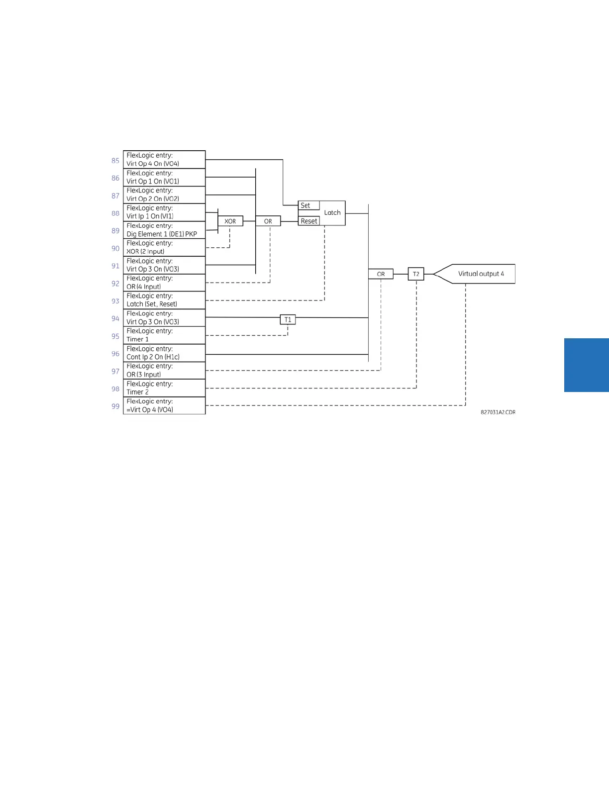
Now check that the selection of parameters produce the required logic by converting the set of parameters into a
logic diagram. The result is shown in the figure, which is compared to the logic for virtual output 4 diagram as a check.
Figure 5-92: FlexLogic equation for virtual output 4
7. Now write the complete FlexLogic expression required to implement the logic, making an effort to assemble the
equation in an order where Virtual Outputs that are used as inputs to operators are created before needed. In cases
where a lot of processing is required to perform logic, this can be difficult to achieve, but in most cases does not cause
problems as all logic is calculated at least four times per power frequency cycle. The possibility of a problem caused by
sequential processing emphasizes the necessity to test the performance of FlexLogic before it is placed in service.
In the following equation, virtual output 3 is used as an input to both latch 1 and timer 1 as arranged in the following
order:
DIG ELEM 2 OP
Cont Ip H1c On
NOT
AND(2)
= Virt Op 3
Virt Op 4 On
Virt Op 1 On
Virt Op 2 On
Virt Ip 1 On
DIG ELEM 1 PKP
XOR(2)
Virt Op 3 On
OR(4)
LATCH (S,R)
Virt Op 3 On
TIMER 1
Cont Ip H1c On
OR(3)