5-198 D30 LINE DISTANCE PROTECTION SYSTEM – INSTRUCTION MANUAL
GROUPED ELEMENTS CHAPTER 5: SETTINGS
5
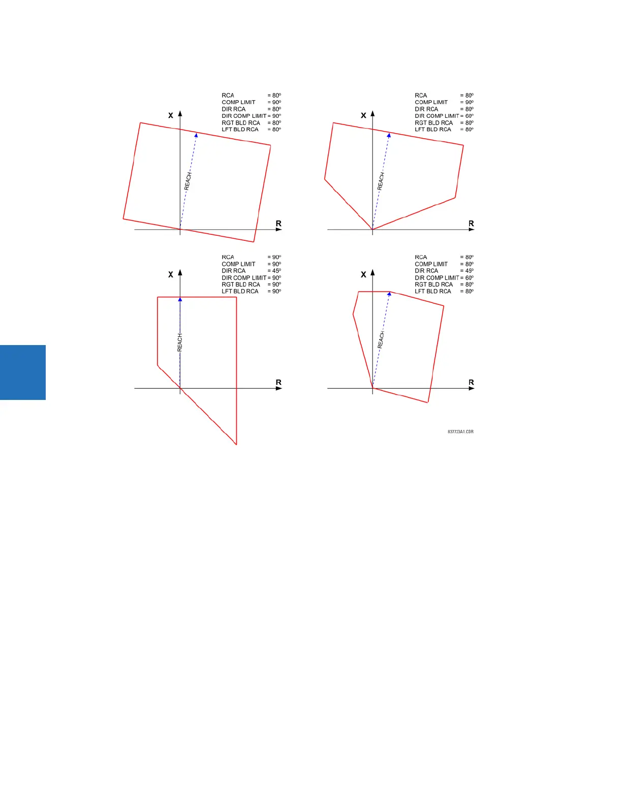
Figure 5-104: Quadrilateral distance characteristic sample shapes
PHS DIST Z1 XFMR VOL CONNECTION — The phase distance elements can be applied to look through a three-phase delta-wye
or wye-delta power transformer. In addition, VTs and CTs can be located independently from one another at different
windings of the transformer. If the potential source is located at the correct side of the transformer, set this setting to
“None.”
This setting specifies the location of the voltage source with respect to the involved power transformer in the direction of
the zone. The following figure illustrates the usage of this setting. In section (a), zone 1 is looking through a transformer
from the delta into the wye winding. Therefore, the Z1 setting is set to “Dy11.” In section (b), Zone 3 is looking through a
transformer from the wye into the delta winding. Therefore, the Z3 setting is set to “Yd1.” The zone is restricted by the
potential point (location of the VTs) as illustrated in (e).
PHS DIST Z1 XFMR CUR CONNECTION — This setting specifies the location of the current source with respect to the involved
power transformer in the direction of the zone. In section (a) of the following figure, zone 1 is looking through a transformer
from the delta into the wye winding. Therefore, the Z1 setting is set to “Dy11.” In section (b), the CTs are located at the same
side as the read point. Therefore, the Z3 setting is set to “None.”
See the Application of Settings chapter for information on calculating distance reach settings in applications involving
power transformers.