CHAPTER 5: SETTINGS GROUPED ELEMENTS
D30 LINE DISTANCE PROTECTION SYSTEM – INSTRUCTION MANUAL 5-205
5
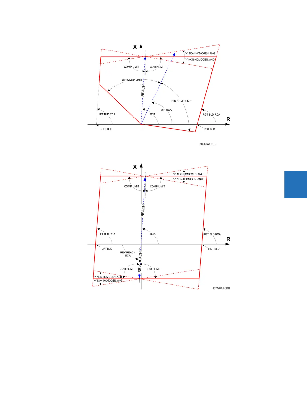
Figure 5-110: Directional quadrilateral ground distance characteristic
Figure 5-111: Non-directional quadrilateral ground distance characteristic
GND DIST Z1 Z0/Z1 MAG — This setting specifies the ratio between the zero-sequence and positive-sequence impedance
required for zero-sequence compensation of the ground distance elements. This setting is available on a per-zone basis,
enabling precise settings for tapped, non-homogeneous, and series compensated lines.
GND DIST Z1 Z0/Z1 ANG — This setting specifies the angle difference between the zero-sequence and positive-sequence
impedance required for zero-sequence compensation of the ground distance elements. The entered value is the zero-
sequence impedance angle minus the positive-sequence impedance angle. This setting is available on a per-zone basis,
enabling precise values for tapped, non-homologous, and series compensated lines.
GND DIST Z1 ZOM/Z1 MAG — The ground distance elements can be programmed to apply compensation for the zero-
sequence mutual coupling between parallel lines. If this compensation is required, the ground current from the parallel line
(3I_0) measured in the direction of the zone being compensated must be connected to the ground input CT of the CT bank