5-250 D30 LINE DISTANCE PROTECTION SYSTEM – INSTRUCTION MANUAL
GROUPED ELEMENTS CHAPTER 5: SETTINGS
5
Table 5-36: Negative-sequence directional unit
Z_offset is the offset impedance, for which magnitude is the OFFSET setting and angle is the FWD ECA.
The negative-sequence voltage must be greater than 0.02 pu to be validated for use as a polarizing signal. Additionally,
when offset impedance is applied and negative-sequence current is above 0.2 pu, compensated negative-sequence
voltage -V_2 + Z_offset x I_2 has to be above 0.02 pu in order to discriminate fault direction; otherwise when negative-
sequence current is less than 0.2 pu, -V_2 is then used as the polarizing signal. If the polarizing signal is not validated,
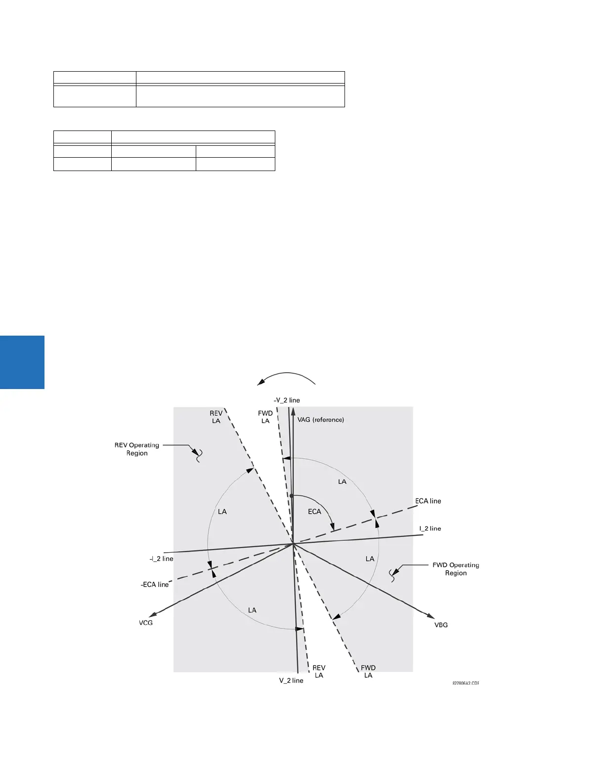
neither forward nor reverse indication is given. The following figure explains the usage of the voltage polarized directional
unit of the element. It shows the phase angle comparator characteristics for a phase A to ground fault, with settings of
ECA = 75° (element characteristic angle = centerline of operating characteristic)
FWD LA = 80° (forward limit angle = ± the angular limit with the ECA for operation)
REV LA = 80° (reverse limit angle = ± the angular limit with the ECA for operation)
The element incorporates a current reversal logic: if the reverse direction is indicated for at least 1.25 of a power system
cycle, the prospective forward indication is delayed by 1.5 of a power system cycle. The element emulates an
electromechanical directional device. Larger operating and polarizing signals result in faster directional discrimination,
bringing more security to the element operation.
Figure 5-139: Negative-sequence directional characteristic
Zero-sequence I
op
= 3 × (|I_0| – K × |I_1|) if |I_1| > 0.8 pu
I
op
= 3 × |I_0| if |I_1| ≤ 0.8 pu
Direction Compared phasors
Forward –V_2+Z_offset× I_2 I_2 × 1∠ECA
Reverse –V_2 + Z_offset × I_2 –(I_2 × 1∠ECA)
Mode Operating current