CHAPTER 5: SETTINGS TRANSDUCER INPUTS/OUTPUTS
D30 LINE DISTANCE PROTECTION SYSTEM – INSTRUCTION MANUAL 5-319
5
DCMA OUTPUT H1 MIN VAL — This setting allows setting the minimum limit for the signal that drives the output. This setting
is used to control the mapping between an internal analog value and the output current. The setting is entered in per-unit
values. The base units are defined in the same manner as the FlexElement base units.
DCMA OUTPUT H1 MAX VAL — This setting allows setting the maximum limit for the signal that drives the output. This setting
is used to control the mapping between an internal analog value and the output current. The setting is entered in per-unit
values. The base units are defined in the same manner as the FlexElement base units.
Three application examples follow.
Example: Power monitoring
A three phase active power on a 13.8 kV system measured via UR-series relay source 1 is to be monitored by the DCmA H1
output of the range of –1 to 1 mA. The following settings are applied on the relay: CT ratio = 1200:5, VT secondary 115, VT
connection is delta, and VT ratio = 120. The nominal current is 800 A primary and the nominal power factor is 0.90. The
power is to be monitored in both importing and exporting directions and allow for 20% overload compared to the nominal.
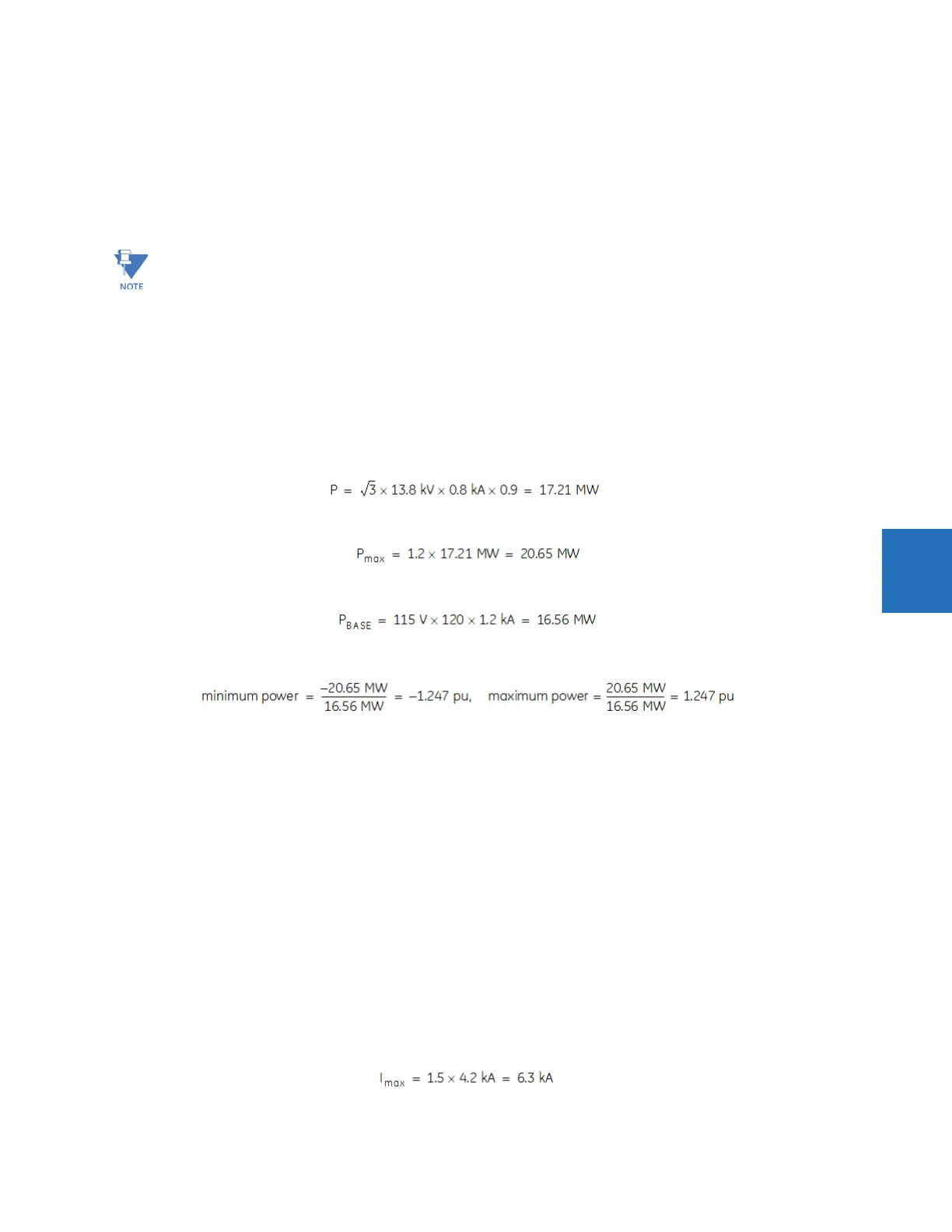
The nominal three-phase power is:
Eq. 5-32
The three-phase power with 20% overload margin is:
Eq. 5-33
The base unit for power (refer to the FlexElements section in this chapter for additional details) is:
Eq. 5-34
The minimum and maximum power values to be monitored (in pu) are:
Eq. 5-35
The following settings are entered:
DCMA OUTPUT H1 SOURCE: “SRC 1 P”
DCMA OUTPUT H1 RANGE: “–1 to 1 mA”
DCMA OUTPUT H1 MIN VAl: “–1.247 pu”
DCMA OUTPUT H1 MAX VAL: “1.247 pu”
With the above settings, the output will represent the power with the scale of 1 mA per 20.65 MW. The worst-case error for
this application can be calculated by superimposing the following two sources of error:
• ±0.5% of the full scale for the analog output module, or ±0.005 x (1-(-1)) x 20.65 MW = ±0.207 MW
• ±1% of reading error for the active power at power factor of 0.9
For example at the reading of 20 MW, the worst-case error is 0.01 × 20 MW + 0.207 MW = 0.407 MW.
Example: Current monitoring
The phase A current (true RMS value) is to be monitored via the H2 current output working with the range from 4 to 20 mA.
The CT ratio is 5000:5 and the maximum load current is 4200 A. The current is to be monitored from 0 A upwards, allowing
for 50% overload.
The phase current with the 50% overload margin is:
Eq. 5-36
The DCMA OUTPUT H1 MIN VAL and DCMA OUTPUT H1 MAX VAL settings are ignored for power factor base units (i.e. if
the DCMA OUTPUT H1 SOURCE is set to FlexAnalog value based on power factor measurement).