6-18 D30 LINE DISTANCE PROTECTION SYSTEM – INSTRUCTION MANUAL
METERING CHAPTER 6: ACTUAL VALUES
6
The metered phase voltage values are displayed in this menu. The "SRC 1" text is replaced by the name programmed by
the user for the associated source (see
SETTINGS SYSTEM SETUP SIGNAL SOURCES).
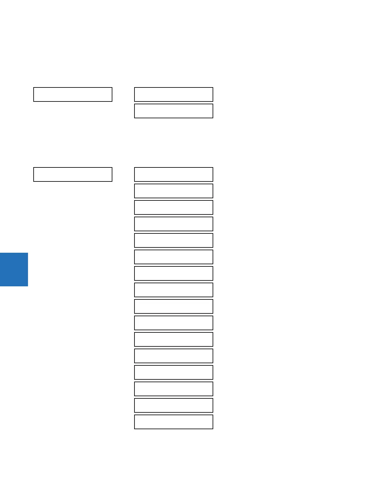
6.4.2.5 Auxiliary voltage metering
ACTUAL VALUES METERING SOURCE SRC 1 AUXILIARY VOLTAGE
The metered auxiliary voltage values are displayed in this menu. The "SRC 1" text is replaced by the name programmed by
the user for the associated source (see
SETTINGS SYSTEM SETUP SIGNAL SOURCES).
6.4.2.6 Power metering
ACTUAL VALUES METERING SOURCE SRC 1 POWER
AUXILIARY VOLTAGE
SRC 1
SRC 1 RMS Vx:
0.00 V
SRC 1 PHASOR Vx:
0.000 V 0.0°
POWER
SRC 1
SRC 1 REAL POWER
3φ: 0.000 W
SRC 1 REAL POWER
φa: 0.000 W
SRC 1 REAL POWER
φb: 0.000 W
SRC 1 REAL POWER
φc: 0.000 W
SRC 1 REACTIVE PWR
3φ: 0.000 var
SRC 1 REACTIVE PWR
φa: 0.000 var
SRC 1 REACTIVE PWR
φb: 0.000 var
SRC 1 REACTIVE PWR
φc: 0.000 var
SRC 1 APPARENT PWR
3φ: 0.000 VA
SRC 1 APPARENT PWR
φa: 0.000 VA
SRC 1 APPARENT PWR
φb: 0.000 VA
SRC 1 APPARENT PWR
φc: 0.000 VA
SRC 1 POWER FACTOR
3φ: 1.000
SRC 1 POWER FACTOR
φa: 1.000
SRC 1 POWER FACTOR
φb: 1.000
SRC 1 POWER FACTOR
φc: 1.000