CHAPTER 9: THEORY OF OPERATION DISTANCE ELEMENTS
D30 LINE DISTANCE PROTECTION SYSTEM – INSTRUCTION MANUAL 9-3
9
• AB phase element — (I
A
– I
B
) × Z – (V
A
– V
B
) and (V
A
– V
B
)_1M
• BC phase element — (I
B
– I
C
) × Z – (V
B
– V
C
) and (V
B
– V
C
)_1M
• CA phase element — (I
C
– I
A
) × Z – (V
C
– V
A
) and (V
C
– V
A
)_1M
• A ground element — I
A
× Z + I_0 × K0 × Z + I
G
× K0M × Z – V
A
and V
A
_1M
• B ground element — I
B
× Z + I_0 × K0 × Z + I
G
× K0M × Z – V
B
and V
B
_1M
• C ground element — I
C
× Z + I_0 × K0 × Z + I
G
× K0M × Z – V
C
and V
C
_1M
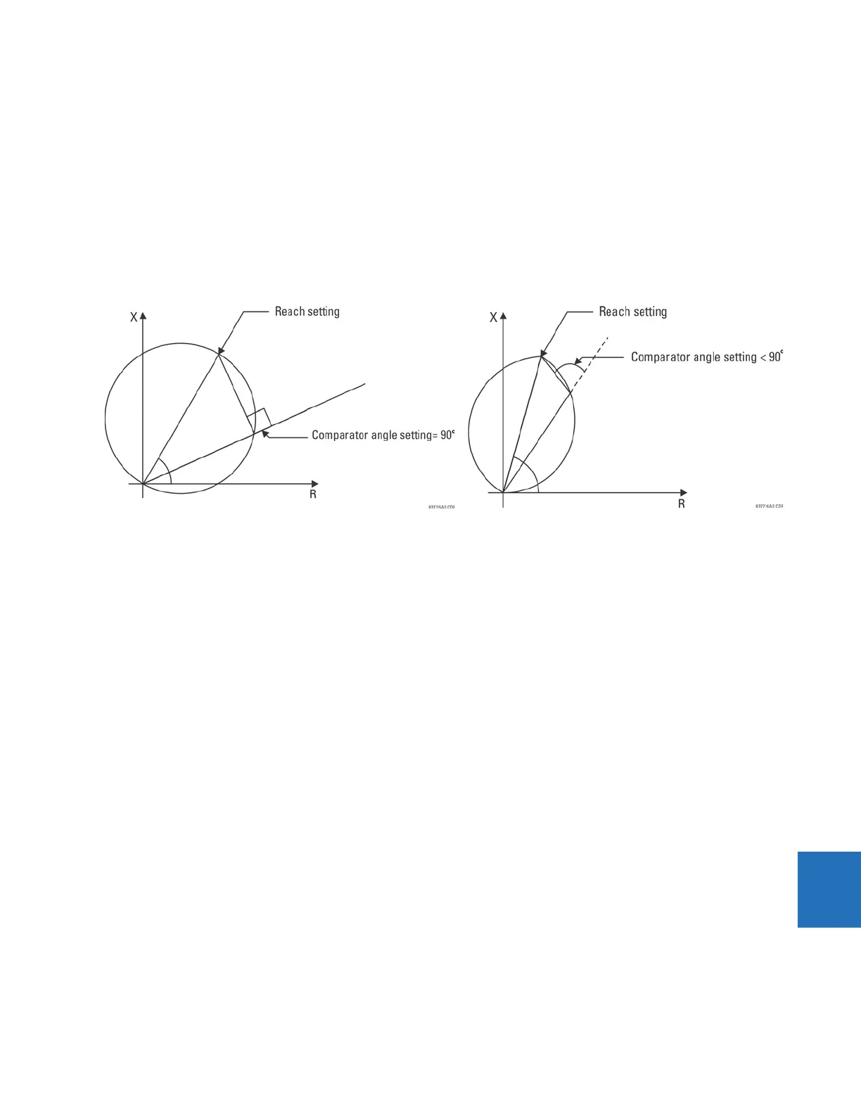
The limit angle of the comparator is adjustable, enabling the user to shape the characteristic as an mho or a lens as shown
in the figure. As explained in the Memory Polarization section, the memory-polarized mho characteristic has an excellent
directional integrity built-in.
Figure 9-1: Mho (left) and lens (right) characteristics
9.1.3.3 Non-directional mho characteristic
The non-directional mho characteristic is achieved by checking the angle between
• AB phase element — (I
A
– I
B
) × Z – (V
A
– V
B
) and (V
A
– V
B
) – (I
A
– I
B
) × Z
REV
• BC phase element — (I
B
– I
C
) × Z – (V
B
– V
C
) and (V
B
– V
C
) – (I
B
– I
C
) × Z
REV
• CA phase element — (I
C
– I
A
) × Z – (V
C
– V
A
) and (V
C
– V
A
) – (I
C
– I
A
) × Z
REV
• A ground element — I
A
× Z + I_0 × K0 × Z + I
G
× K0M × Z – V
A
and V
A
– (I
A
× Z
REV
+ I_0 × K0 × Z
REV
+ I
G
× K0M × Z
REV
)
• B ground element — I
B
× Z + I_0 × K0 × Z + I
G
× K0M × Z – V
B
and V
B
– (I
B
× Z
REV
+ I_0 × K0 × Z
REV
+ I
G
× K0M × Z
REV
)
• C ground element — I
C
× Z + I_0 × K0 × Z + I
G
× K0M × Z – V
C
and V
C
– (I
C
× Z
REV
+ I_0 × K0 × Z
REV
+ I
G
× K0M × Z
REV
)
9.1.3.4 Mho reactance characteristic for directional applications
The reactance characteristic is achieved by checking the angle between
• AB phase element — (I
A
– I
B
) × Z – (V
A
– V
B
) and (I
A
– I
B
) × Z
• BC phase element — (I
B
– I
C
) × Z – (V
B
– V
C
) and (I
B
– I
C
) × Z
• CA phase element — (I
C
– I
A
) × Z – (V
C
– V
A
) and (I
C
– I
A
) × Z
• A ground element — I
A
× Z + I_0 × K0 × Z + I
G
× K0M × Z – V
A
and I_0 × Z
• B ground element — I
B
× Z + I_0 × K0 × Z + I
G
× K0M × Z – V
B
and I_0 × Z
• C ground element — I
C
× Z + I_0 × K0 × Z + I
G
× K0M × Z – V
C
and I_0 × Z
If the mho characteristic is selected, the limit angle of the comparator is adjustable concurrently with the limit angle of the
mho characteristic, resulting in a tent shape complementing the lens characteristic being effectively applied.
9.1.3.5 Quadrilateral reactance characteristic for directional applications
The quadrilateral reactance characteristic is achieved by checking the angle between
• AB phase element — (I
A
– I
B
) × Z – (V
A
– V
B
) and (I
A
– I
B
) × Z