CHAPTER 3: INSTALLATION WIRING
D30 LINE DISTANCE PROTECTION SYSTEM – INSTRUCTION MANUAL 3-25
3
Figure 3-21: Contact input and output module wiring (Sheet 3 of 3)
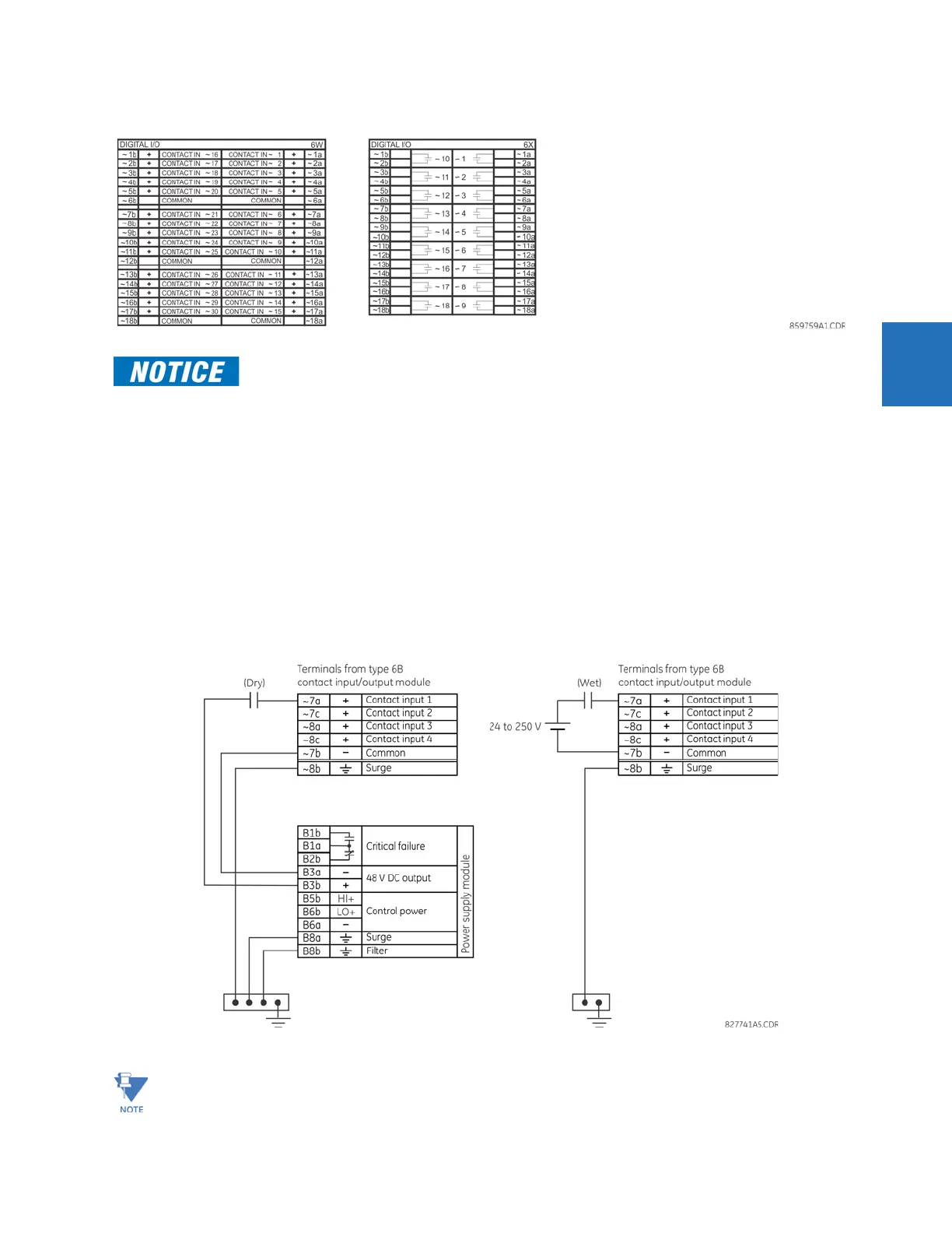
3.3.6.1 Contact inputs
A dry contact has one side connected to terminal B3b. This is the positive 48 V DC voltage rail supplied by the power supply
module. The other side of the dry contact is connected to the required contact input terminal. Each contact input group
has its own common (negative) terminal that must be connected to the DC negative terminal (B3a) of the power supply
module. When a dry contact closes, a current of 1 to 3 mA flows through the associated circuit.
A wet contact has one side connected to the positive terminal of an external DC power supply. The other side of this
contact is connected to the required contact input terminal. If a wet contact is used, then the negative side of the external
source must be connected to the relay common (negative) terminal of each contact group. The maximum external source
voltage for this arrangement is 300 V DC.
The voltage threshold at which each group of four contact inputs detects a closed contact input is programmable as
17 V DC for 24 V sources, 33 V DC for 48 V sources, 84 V DC for 110 to 125 V sources, and 166 V DC for 250 V sources.
Figure 3-22: Dry and wet contact input connections
For proper functionality, observe the polarity shown in the figures for all contact input and output
connections.
Where a tilde “~” symbol appears, substitute the slot position of the module.