Chapter 1. Installation
2 DigitalFlow™ GF868 Startup Guide (1 and 2-Channel)
1.3 Site Considerations
Since the relative physical locations of the flowcell(s) and the GF868 electronics are important, use the guidelines
given in this section when planning your GF868 system installation.
1.3.1 Electronics Console Location
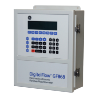
Normally, the GF868 electronics enclosure is a Type-4X weather-resistant, dust-tight, indoor/outdoor type. (Other
enclosure options are described in Appendix C.) Typically, the electronics console is mounted in a meter shed. If it is
not, select a location that allows you access to your meter for programming, testing, and servicing.
Note: For compliance with the European Union’s Low Voltage Directive, this unit requires an external power
disconnect device such as a switch or circuit breaker. The disconnect device must be marked as such, clearly
visible, directly accessible, and located within 6 ft (1.8 m) of the GF868.
1.3.2 Flowcell Location
The pipeline flowcell consists of the flowmeter transducers and any pressure and temperature transducers that may be
used as part of the flowmeter system. Ideally, the section of pipe chosen as the flowcell should be a pipe section with
easy access; for example, a long stretch of pipe that is above ground. However, if the flowcell must be on an
underground pipe, dig a pit around the pipe to facilitate the transducer mechanisms.
1.3.3 Transducer Locations
For a given gas and pipe, the Model GF868’s accuracy depends primarily on the location and alignment of the
transducers on the pipe. In addition to accessibility, when planning for transducer location, consider the following
guidelines:
• Locate the transducers so that there are at least 20 pipe diameters of straight, undisturbed flow upstream and 10
pipe diameters of straight, undisturbed flow downstream from the measurement point. To ensure undisturbed flow,
avoid: sources of turbulence in the fluid such as valves, flanges, expansions and elbows; swirl; and dips or low
spots in which condensed liquid may collect.
• Because condensate or sediment that collects at the bottom of the pipe may cause increased attenuation of the
ultrasonic signal, locate the transducers on the side of a horizontal pipe, where possible. If limited pipe access
necessitates top-mounted transducers and the sound beam path includes a reflection, shift the transducers to at least
10° off top center. This will minimize the influence of any sediment on the reflected ultrasonic signals.
1.3.4 Cable Lengths
Locate the transducers as close as possible to the electronics console. The factory can supply transducer cables up to
500 ft (153 m) in length. For longer distances, consult the factory.
 Loading...
