DigitalFlow™ GF868 Startup Guide (1 and 2-Channel) 15
Chapter 1. Installation
1.7.7 Wiring the Totalizer/ Frequency Outputs
The GF868 can accommodate 1 to 6 totalizer/frequency outputs option cards. Each totalizer/frequency outputs option
card provides four outputs (A, B, C, and D) that can be used as either totalizer or frequency outputs.
Each totalizer/frequency output requires two wires. Wire this terminal block in accordance with the pin number
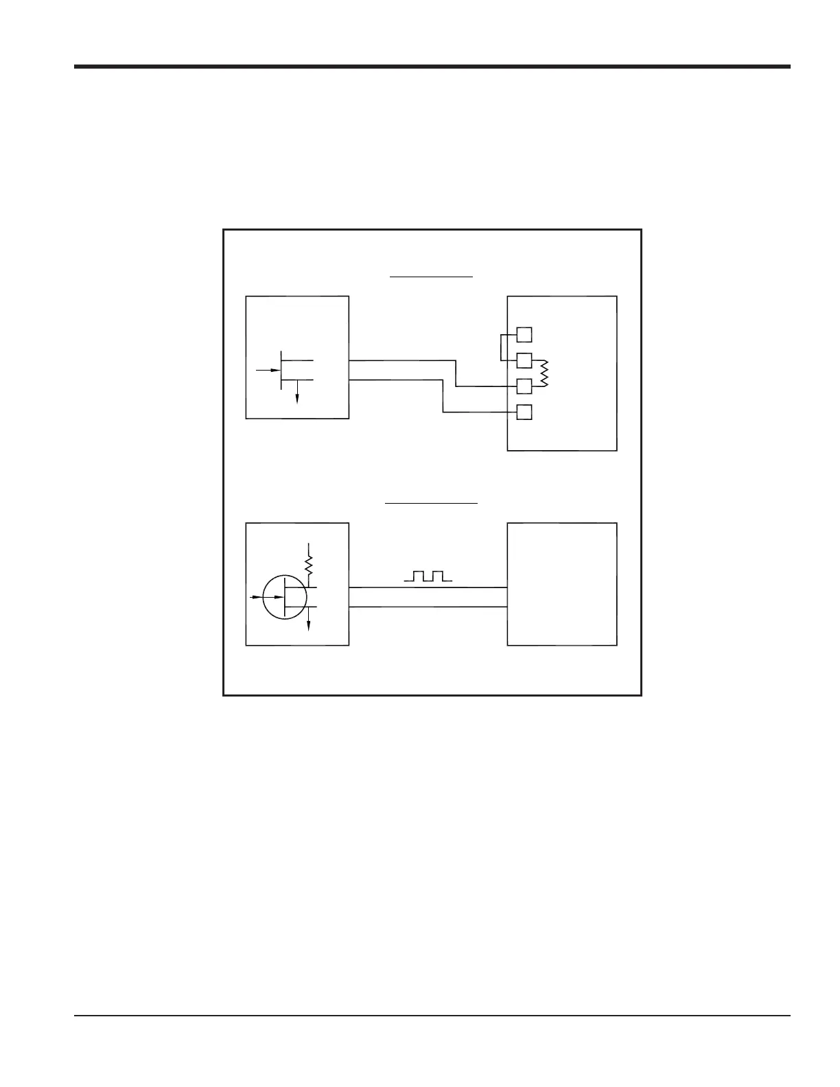
assignments shown in Figure 9 on page 18. Figure 7 shows sample wiring diagrams for the totalizer/frequency outputs.
Figure 7: Totalizer/Frequency Output Wiring
1.7.8 Wiring the RTD Inputs
The GF868 can accommodate 1 to 6 RTD (Resistance Temperature Device) inputs card(s). Each RTD inputs card
provides two direct RTD inputs (A and B).
Each RTD input requires three wires. Feed the wires through one of the conduit holes on the bottom center of the
enclosure. Connect the wires to the 8-pin RTD inputs option card terminal block as shown in Figure 9 on page 18.
NO
C
IN
Common
Volts –
(Common)
Volts +
(Int. Pwr. Sup.)
NO
C
+5V
200
:
Model GF868
Model GF868
Pulse Counter
Frequency Counter
Totalizer Output
Frequency Output
Load
Max. Current: 4A
Max. Voltage: 150V
Isolation Voltage: 500V
Max. Load Power: 10W In
C = Isolated Return
C = Isolated Return

 Loading...


