GE Multilin G30 Generator Protection System 4-17
4 HUMAN INTERFACES 4.3 FACEPLATE INTERFACE
4
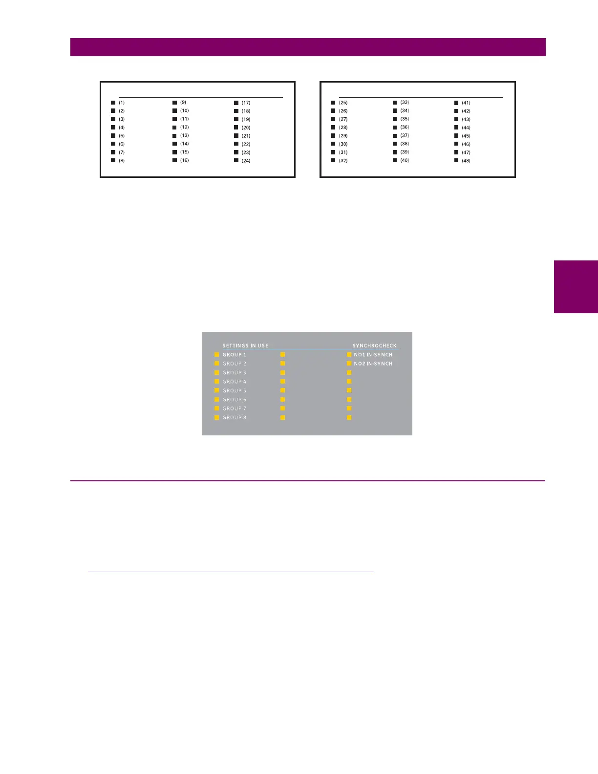
Figure 4–20: LED PANELS 2 AND 3 (INDEX TEMPLATE)
DEFAULT LABELS FOR LED PANEL 2:
The default labels are intended to represent:
• GROUP 1...6: The illuminated GROUP is the active settings group.
• SYNCHROCHECK NO1(4) IN-SYNCH: Voltages have satisfied the synchrocheck element.
The relay is shipped with the default label for the LED panel 2. The LEDs, however, are not pre-programmed. To match the
pre-printed label, the LED settings must be entered as shown in the User-programmable LEDs section of chapter 5. The
LEDs are fully user-programmable. The default labels can be replaced by user-printed labels for both panels as explained
in the following section.
Figure 4–21: LED PANEL 2 (DEFAULT LABELS)
4.3.3 CUSTOM LABELING OF LEDS
a) ENHANCED FACEPLATE
The following procedure requires these pre-requisites:
• EnerVista UR Setup software is installed and operational
• The G30 settings have been saved to a settings file
• The G30 front panel label cutout sheet (GE Multilin part number 1006-0047) has been downloaded from
http://www.gegridsolutions.com/products/support/ur/URLEDenhanced.doc
and printed
• Small-bladed knife
To create custom LED labels for the enhanced front panel display:
1. Start the EnerVista UR Setup software.
USER-PROGRAMMABLE LEDS USER-PROGRAMMABLE LEDS
842782A1.CDR