9-6 G30 Generator Protection System GE Multilin
9.1 SETTING EXAMPLE 9 APPLICATION OF SETTINGS
9
Enter the following values through EnerVista UR Setup (or alternately, through the front panel SETTINGS SYSTEM SETUP
AC INPUTS VOLTAGE BANK F5 menu):
9.1.3 POWER SYSTEM
Frequency tracking should always be enabled for generator applications. Make the following power system parameters
changes via EnerVista UR Setup or through the
SETTINGS SYSTEM SETUP POWER SYSTEM VOLTAGE BANK F5
menu:
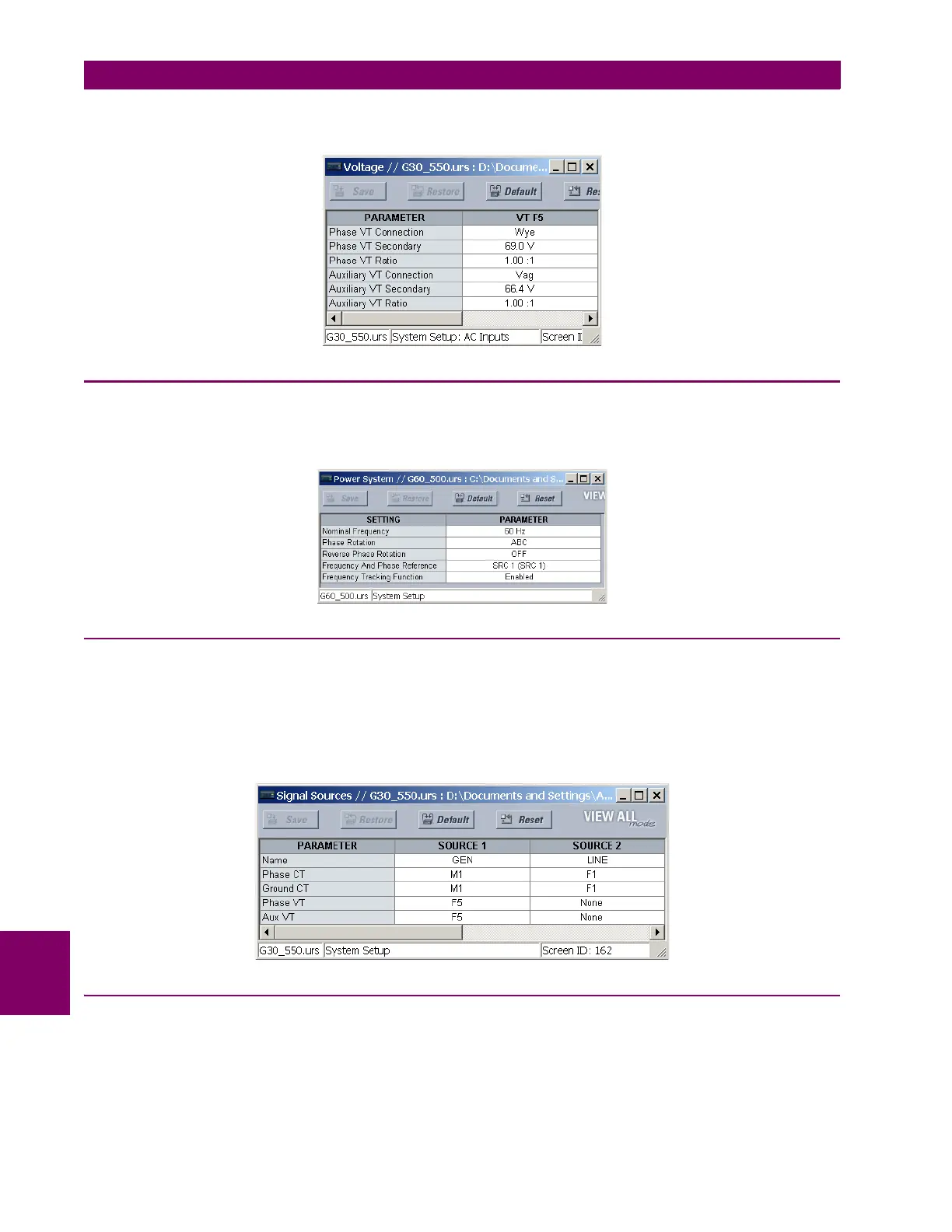
9.1.4 SIGNAL SOURCES
Two sources are required for this application example. The “LINE” source uses the phase and auxiliary VT inputs and the
CT input wired to the generator output CT. The “GEN” source uses the phase VT inputs and the CT input wired to the gen-
erator neutral CT. Including the phase VT inputs for both sources allows the user to choose the location of elements that
use both voltage and current. Elements using the auxiliary VT input are assigned to the “GEN” source.
Make the following changes through EnerVista UR Setup or through the
SETTINGS SYSTEM SETUP SOURCE 1 and
the
SETTINGS SYSTEM SETUP SOURCE 2 menus:
9.1.5 GENERATOR UNBALANCE
Stage 1 of the generator unbalance element is typically used to trip the generator. In this example, the I
2
capability of the
machine is 8% and the I
2
2
T capability is 10. The generator nominal current is:
(EQ 9.5)
I
nom pu()
I
nom
primary
CT primary
---------------------------------
6800 A
8000 A
-------------------
0.85 pu===