GE Multilin G30 Generator Protection System 5-149
5 SETTINGS 5.5 FLEXLOGIC
5
The FLEXELEMENT 1 HYSTERESIS setting defines the pickup–dropout relation of the element by specifying the width of the
hysteresis loop as a percentage of the pickup value as shown in the FlexElement direction, pickup, and hysteresis diagram.
The FLEXELEMENT 1 DT UNIT setting specifies the time unit for the setting FLEXELEMENT 1 dt. This setting is applicable only if
FLEXELEMENT 1 COMP MODE is set to “Delta”. The FLEXELEMENT 1 DT setting specifies duration of the time interval for the
rate of change mode of operation. This setting is applicable only if FLEXELEMENT 1 COMP MODE is set to “Delta”.
This FLEXELEMENT 1 PKP DELAY setting specifies the pickup delay of the element. The FLEXELEMENT 1 RST DELAY setting
specifies the reset delay of the element.
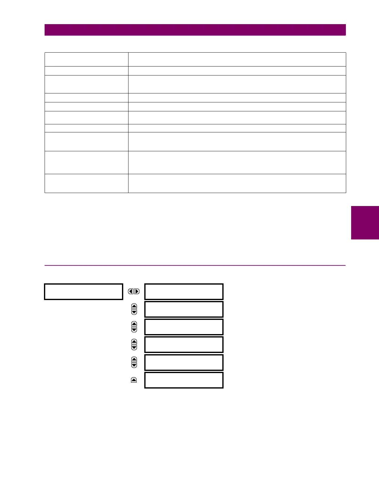
5.5.8 NON-VOLATILE LATCHES
PATH: SETTINGS FLEXLOGIC NON-VOLATILE LATCHES LATCH 1(16)
The non-volatile latches provide a permanent logical flag that is stored safely and will not reset upon reboot after the relay
is powered down. Typical applications include sustaining operator commands or permanently block relay functions, such as
Autorecloser, until a deliberate interface action resets the latch. The settings element operation is described below:
• LATCH 1 TYPE: This setting characterizes Latch 1 to be Set- or Reset-dominant.
• LATCH 1 SET: If asserted, the specified FlexLogic operands 'sets' Latch 1.
• LATCH 1 RESET: If asserted, the specified FlexLogic operand 'resets' Latch 1.
SENSITIVE DIR POWER
(Sns Dir Power)
P
BASE
= maximum value of 3 × V
BASE
× I
BASE
for the +IN and –IN inputs of the sources
configured for the sensitive power directional element(s).
SOURCE CURRENT I
BASE
= maximum nominal primary RMS value of the +IN and –IN inputs
SOURCE ENERGY
(Positive and Negative Watthours,
Positive and Negative Varhours)
E
BASE
= 10000 MWh or MVAh, respectively
SOURCE POWER P
BASE
= maximum value of V
BASE
× I
BASE
for the +IN and –IN inputs
SOURCE VOLTAGE V
BASE
= maximum nominal primary RMS value of the +IN and –IN inputs
SYNCHROCHECK
(Max Delta Volts)
V
BASE
= maximum primary RMS value of all the sources related to the +IN and –IN inputs
VOLTS PER HERTZ BASE = 1.00 pu
XFMR DIFFERENTIAL CURRENT
(Xfmr Iad, Ibd, and Icd Mag)
I
BASE
= maximum primary RMS value of the +IN and -IN inputs
(CT primary for source currents, and transformer reference primary current for transformer
differential currents)
XFMR DIFFERENTIAL
HARMONIC CONTENT
(Xfmr Harm2 Iad, Ibd, and Icd Mag)
(Xfmr Harm5 Iad, Ibd, and Icd Mag)
BASE = 10%
XFMR RESTRAINING CURRENT
(Xfmr Iar, Ibr, and Icr Mag)
I
BASE
= maximum primary RMS value of the +IN and -IN inputs
(CT primary for source currents, and transformer reference primary current for transformer
differential currents)
LATCH 1
LATCH 1
FUNCTION: Disabled
Range: Disabled, Enabled
MESSAGE
LATCH 1 TYPE:
Reset Dominant
Range: Reset Dominant, Set Dominant
MESSAGE
LATCH 1 SET:
Off
Range: FlexLogic operand
MESSAGE
LATCH 1 RESET:
Off
Range: FlexLogic operand
MESSAGE
LATCH 1
TARGET: Self-reset
Range: Self-reset, Latched, Disabled
MESSAGE
LATCH 1
EVENTS: Disabled
Range: Disabled, Enabled
Table 5–20: FLEXELEMENT BASE UNITS