6-22 G30 Generator Protection System GE Multilin
6.3 METERING 6 ACTUAL VALUES
6
(EQ 6.3)
The harmonics are a percentage of the fundamental signal obtained as a ratio of harmonic amplitude to fundamental ampli-
tude multiplied by 100%. The total harmonic distortion (THD) is the ratio of the total harmonic content to the fundamental:
(EQ 6.4)
Voltage harmonics are calculated only for Wye connected phase VTs. Ensure the SYSTEM SETUP AC INPUTS
VOLTAGE BANK F5 PHASE VT XX CONNECTION setting is “Wye” to enable voltage harmonics metering.
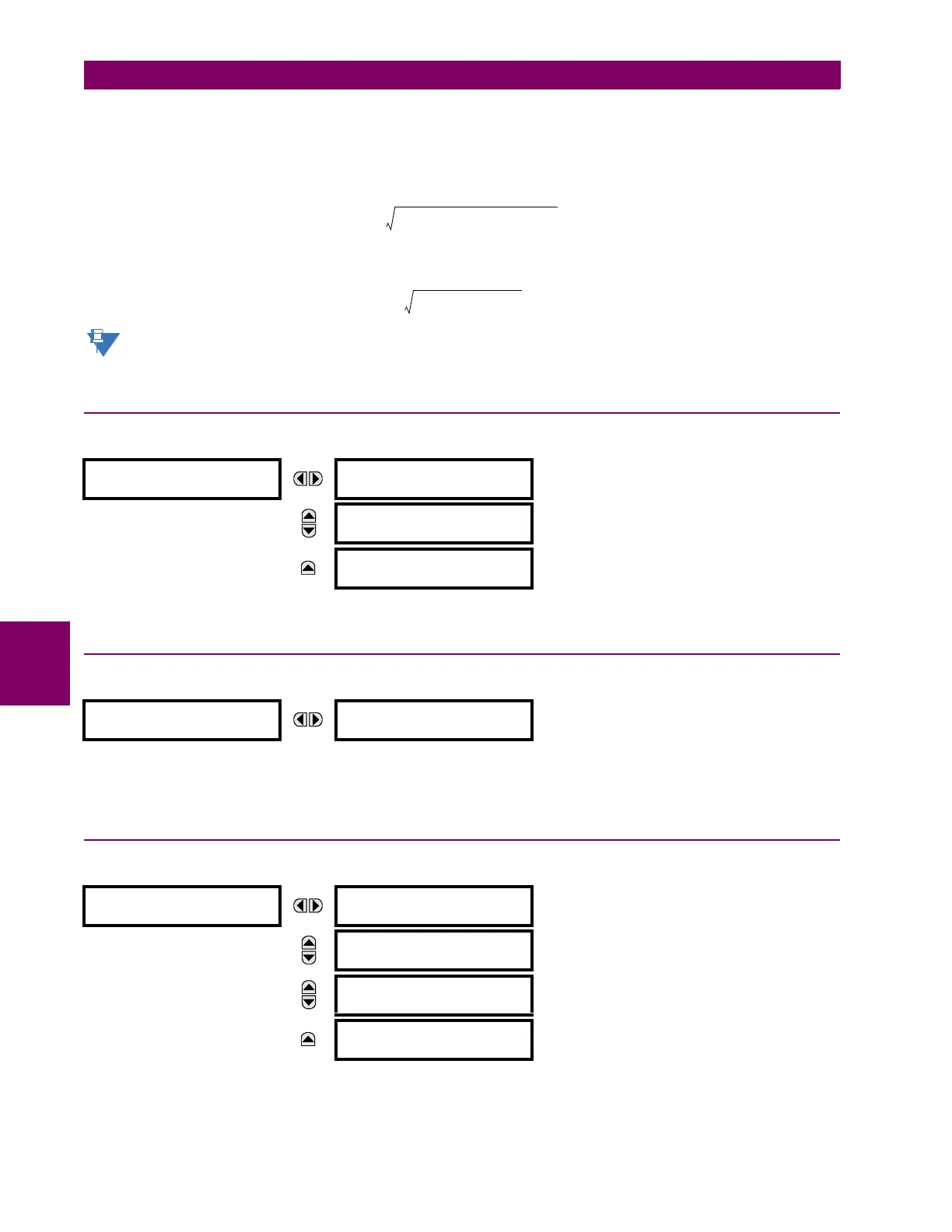
6.3.4 SYNCHROCHECK
PATH: ACTUAL VALUES METERING SYNCHROCHECK SYNCHROCHECK 1(4)
If a synchrocheck function setting is "Disabled", the corresponding actual values menu item is not displayed.
6.3.5 TRACKING FREQUENCY
PATH: ACTUAL VALUES METERING TRACKING FREQUENCY
The tracking frequency is displayed here. The frequency is tracked based on the selection of the reference source with the
FREQUENCY AND PHASE REFERENCE setting in the SETTINGS SYSTEM SETUP POWER SYSTEM menu. See the Power
System section of chapter 5 for details.
6.3.6 FREQUENCY RATE OF CHANGE
PATH: ACTUAL VALUES METERING FREQUENCY RATE OF CHANGE
The metered frequency rate of change for the frequency rate of change elements is shown here.
SYNCHROCHECK 1
SYNCHROCHECK 1 DELTA
VOLT: 0.000 V
MESSAGE
SYNCHROCHECK 1 DELTA
PHASE: 0.0°
MESSAGE
SYNCHROCHECK 1 DELTA
FREQ: 0.00 Hz
TRACKING FREQUENCY
TRACKING FREQUENCY:
60.00 Hz
FREQUENCY RATE
OF CHANGE
FREQUENCY RATE OF
CHANGE 1: 0.00 Hz/s
MESSAGE
FREQUENCY RATE OF
CHANGE 2: 0.00 Hz/s
MESSAGE
FREQUENCY RATE OF
CHANGE 3: 0.00 Hz/s
MESSAGE
FREQUENCY RATE OF
CHANGE 4: 0.00 Hz/s
F
real
mh,()
2
N
----
fm k–() h ω
0
tk()⋅⋅()cos⋅()
k
=
F
imag
mh,()
2
N
----
fm k–()h ω
0
tk()⋅⋅()sin⋅()
k
=
F
ampl
mh,() F
real
mh,()
2
F
imag
mh,()
2
+=