GE Multilin G30 Generator Protection System 9-5
9 APPLICATION OF SETTINGS 9.1 SETTING EXAMPLE
9
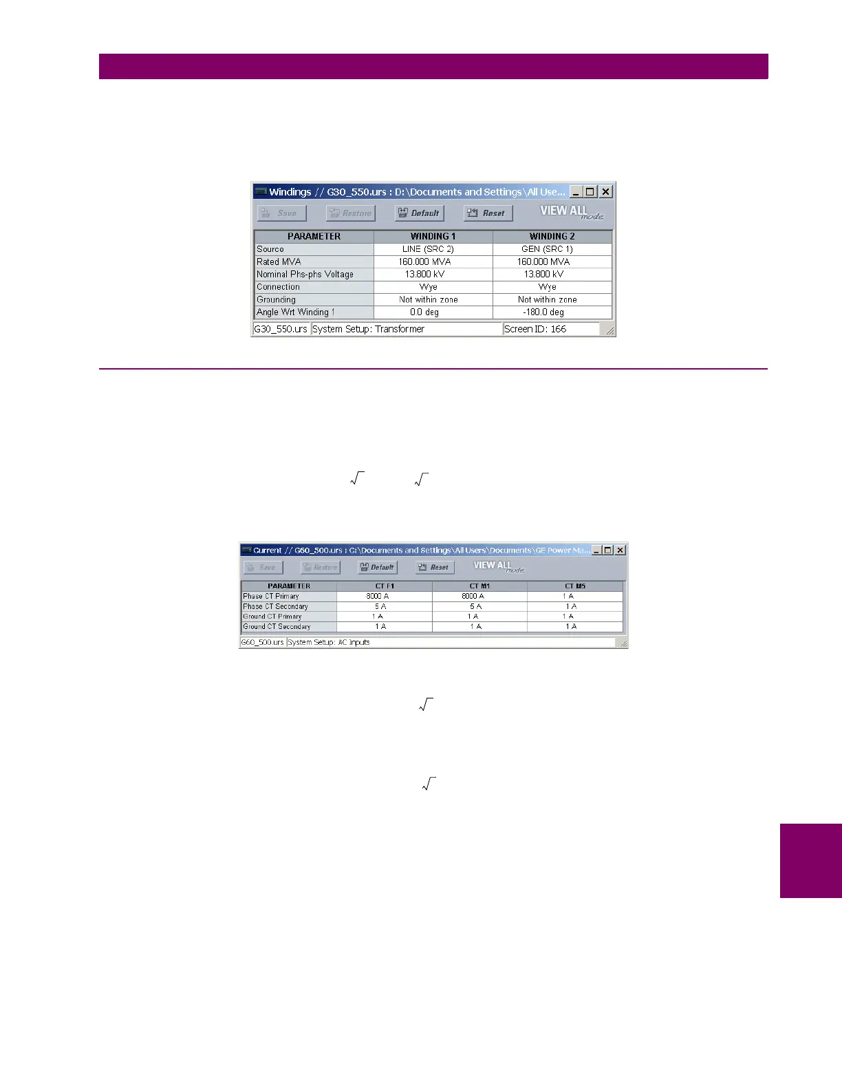
The G30 requires the use of the transformer windings settings for the differential element, even if the differential is applied
only as a stator differential for the generator. These settings ensure that the differential element operates with the correct
phase shifts, and applies the correct magnitude compensation. Loss of excitation and reverse power can be assigned to
either source. Since there is no transformer involved, the phase shift to enter is the –180° phase shift due to the CT polari-
ties and connections.
9.1.2 SYSTEM SETUP
Ideally, the CTs should be selected so the generator nominal current is 80 to 85% of CT primary. The following settings are
entered for the example system. The M5 bank and the ground CT input on each of the groups are unused in this example.
The nominal current is given by:
(EQ 9.1)
Make the following settings changes in EnerVista UR Setup (or alternately, via the front panel through the SYSTEM SETUP
AC INPUTS CURRENT BANK F1 and the SYSTEM SETUP AC INPUTS CURRENT BANK M1 menus).
For the example system, the voltage settings are calculated as follows:
PHASE VT SECONDARY = (EQ 9.2)
PHASE VT RATIO = (EQ 9.3)
NEUTRAL VT RATIO = (EQ 9.4)
I
nom
13.8 kV()
S
nom
3V
nom
---------------------
162 10
6
× VA
3 13.8 10
3
×× V
-----------------------------------------------
6800 A== =
18000 V
3
----------------------
120 V
13800 V
----------------------
× 69 V=
13800 V
120 V
----------------------
115=
13800 V
3 240 V×
-----------------------------
33=