GE Multilin G30 Generator Protection System 5-205
5 SETTINGS 5.6 GROUPED ELEMENTS
5
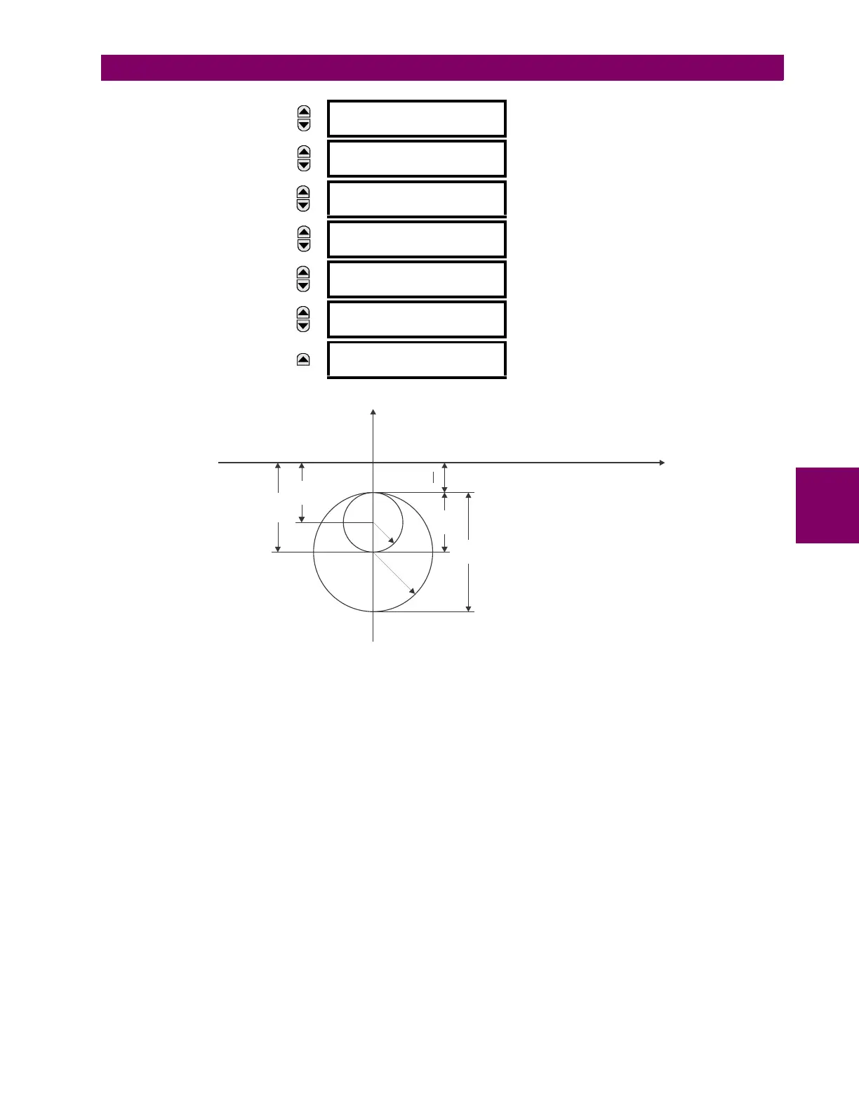
The operating characteristic is shaped out of two offset mho circles shifted down along the imaginary axis as shown below.
Figure 5–91: LOSS OF EXCITATION OPERATING CHARACTERISTICS
STAGE 1 SETTINGS:
The stage 1 characteristic is typically set to detect a loss of excitation for load conditions of 30% of the nominal or higher.
This is achieved with a mho element with a diameter equal to the base impedance of the machine and an offset equal to
half the machine transient reactance (X
′
d).
(EQ 5.52)
The stage 1 element should be time delayed to allow for blocking by the VT fuse failure element (50 ms).
STAGE 2 SETTINGS:
The stage 2 characteristic is typically set to detect a loss of excitation for all load conditions. This is achieved with a mho
element with a diameter equal to the synchronous reactance of the machine and an offset equal to half the machine tran-
sient reactance (X
′
d).
(EQ 5.53)
During stable power swing conditions the positive-sequence impedance may momentarily enter the stage 2 characteristic.
For security of the function under such conditions, it is recommended to delay stage 2 by a minimum of 0.5 seconds.
MESSAGE
LOSS OF EXCITATION
RADIUS 2: 10.00 ohm
Range: 0.10 to 300.00 ohms in steps of 0.01
MESSAGE
LOSS OF EXCITATION
V SUPV 2: Enabled
Range: Disabled, Enabled
MESSAGE
LOSS OF EXCITATION
PKP DELAY2: 0.500 s
Range: 0.000 to 65.535 s in steps of 0.01
MESSAGE
LOSS OF EXCITATION
UV SUPV: 0.700 pu
Range: 0.000 to 1.250 pu in steps of 0.001
MESSAGE
LOSS OF EXCIT BLK:
Off
Range: FlexLogic operand
MESSAGE
LOSS OF EXCITATION
TARGET: Self-reset
Range: Self-reset, Latched, Disabled
MESSAGE
LOSS OF EXCITATION
EVENTS: Disabled
Range: Disabled, Enabled
830711A1.CDR
C1
Zb
Xd
R
C1
R1
C2
R2
Zb
X’d
Xd
= Center of element 1 = (Zb + X’d) / 2
= Radius of element 1 = Zb / 2
= Center of element 2 = (Xd + X’d) / 2
= Radius of element 2 = Xd / 2
= Base impedance of the machine
= Transient reactance of the machine
= Synchronous reactance of the machine
X
X’d
2
R1
R2
C2
CENTER 1
Zb X′d+
2
-----------------------
, RADIUS 1
Zb
2
-------
==
CENTER 2
Xd X′d+
2
-----------------------
, RADIUS 1
Xd
2
-------
==