GE Multilin G30 Generator Protection System 5-213
5 SETTINGS 5.6 GROUPED ELEMENTS
5
• 3RD HARM NTRL UV PICKUP: This setting specifies the pickup level for the magnitude of the third harmonic of the
neutral voltage. This setting is entered in pu of the nominal auxiliary voltage.
The magnitude of the third harmonic voltage at the neutral point is monitored in the ACTUAL VALUES METERING
STATOR GROUND menu. Measuring the actual value of the operating quantity for a specific machine under variety of
load conditions may be helpful when selecting the pickup threshold for this feature.
• 3RD HARM NTRL UV MAX POWER: This setting specifies the maximum active power that inhibits this protection
function. If the measured power is below this setting but above the
3RD HARM NTRL UV MIN POWER setting the element
shall not operate. This setting applies to three-phase power and is entered in pu. The base quantity is 3-phase power
on primary side, which is calculated as x Phase CT Primary x Phase VT Ratio x Phase VT Secondary in case of
delta connected VTs; and 3 x Phase CT Primary x Phase VT Ratio x Phase VT Secondary in case of wye connected
VTs.
For example, a setting of 20% for a 200 MW machine, is 0.20 × 200 MW = 40 MW. If 7.967 kV is a primary VT voltage
and 10 kA is a primary CT current, the source pu quantity is 239 MVA, and thus, the pu power setting is 40 MW /
239 MVA = 0.167 pu.
• 3RD HARM NTRL UV MIN POWER: This setting specifies the minimum active power that inhibits this protection func-
tion. If the measured power is above this setting but below the
3RD HARM NTRL UV MAX POWER setting the element shall
not operate. If the
3RD HARMONIC NTRL UV MIN POWER is set to “0.00 pu”, then the element does not operate for all
power values less than the 3RD HARM NTRL UV MAX POWER setting.
This setting applies to three-phase power and is entered in pu. The base quantity is 3-phase power on primary side,
which is calculated as x Phase CT Primary x Phase VT Ratio x Phase VT Secondary in case of delta connected
VTs; and 3 x Phase CT Primary x Phase VT Ratio x Phase VT Secondary in case of wye connected VTs.
If the VTs are located on the high-voltage (HV) side of the transformer, then the source should be configured using
CTs that are also on the HV side. Correspondingly, if the VTs are located on the low-voltage (LV) side of the trans-
former, then the source should be configured using CTs that are also on the LV side. In both cases, the CT polarity
should produce a positive power measurement when the machine is generating.
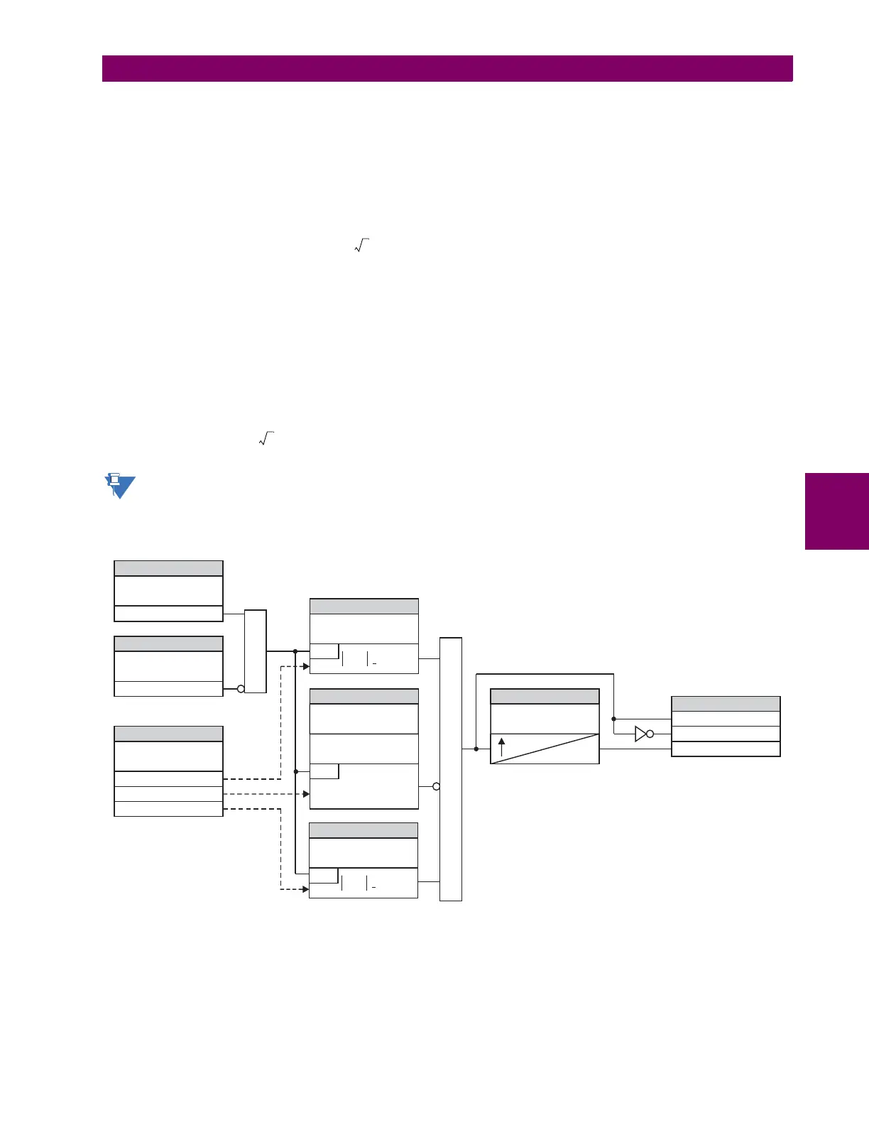
Figure 5–97: THIRD HARMONIC NEUTRAL UNDERVOLTAGE SCHEME LOGIC
830005A5.CDR
SETTING
FLEXLOGIC OPERANDS
3RD HARM NTRL UV
FUNCTION:
3RD HARM NTRL UV PKP
3RD HARM NTRL UV DPO
Enabled = 1
AND
3RD HARM NTRL UV BLK:
Off = 0
SETTING
SETTINGS
SETTINGS SETTINGS
3RD HARM NTRL UV
PICKUP:
RUN
RUN
Vaux < Pickup
3 Phase Real Power
V_1
AND
3RD HARM NTRL UV
MAX POWER:
Min < 3 Phase Power < Max
3RD HARM NTRL UV
MIN POWER:
SETTING
Vaux (3rd harmonic)
STATOR GROUND
SOURCE:
3RD HARM NTRL UV
PKP DELAY:
20 ms
3RD HARM NTRL UV OP
SETTINGS
3RD HARM NTRL UV
VOLT SUPV:
RUN
V_1 > Pickup