– 43 –
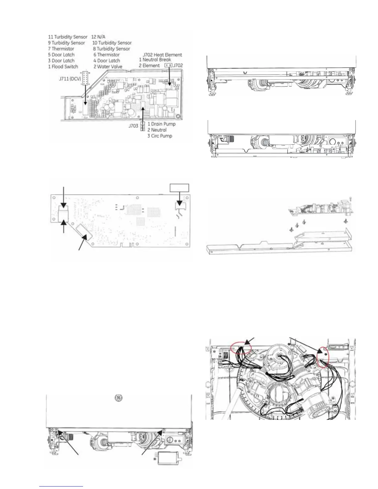
Top Side of Main Control
Bottom Side of Main Control
WARNING: GE Factory Service Technicians are
REQUIRED to follow Lockout / Tagout (LOTO) 6
Step Process prior to beginning repair.
To Access Main Control Board:
1. Remove power to the dishwasher.
2. Remove the toe kick panel.
3. Remove the door (optional).
4. Remove the junction box cover.
5. Remove two 1/4 in. hex head screws on control
box
Remove two 1/4 in. hex
head screws
J722 Door Connector
(some models)
ACM
Connector
J721 Door
Connector (some
models)
Power Supply
1. L1 Line
2. Neutral
3. Earth / Ground
J701
1 2 3
6. Pull down on the bottom cover at the front of
control box. While pulling down on the front of
the bottom cover, slide the cover forward to
clear the back lip and junction box bracket.
7. Pull cover and control forward, taking care not
to damage the board or the wiring.
8. To remove the control board from the bottom
cover, remove the ground screw and release the
IRXUVWDQGRȺV
9. Use care when reinstalling the main control
board to prevent wire pinching. Make sure the
harnesses are routed properly, through the
access ports in the control area and above the
sump hoses to keep them from snagging on the
ÀRRU
10. All ground screws must be reinstalled
Harness wire pinch
potential areas
 Loading...