Product Introduction
7
User Manual V1.3-2022-11-18
3.4 Appearance
3.4.1 Parts
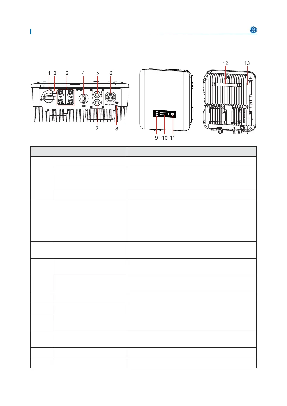
No. Parts Description
1 DC Switch Start or stop DC input.
2 DC Switch Lock
2QO\IRU$XVWUDOLD7XUQWKH'&VZLWFKWR2))DQG
lock it to avoid electric shock when you have to work
on the inverter.
3 PV Input Terminal Used to connect the PV module DC input cables.
4
&203RUWIRUFRPPXQLFDWLRQ
module, USB-RS485 cable or
USB.
• Connect a communication module like Bluetooth,
:L)L/$1:L)L*356*HWF7KHPRGXOHW\SH
PD\GLࢆHUGHSHQGLQJRQDFWXDOQHHGV
• Connect the USB-RS485 cable in Brazil.
• Update the software version of the inverter using
D86%ࢊDVKGULYHU
5
&203RUWIRU56UHPRWH
shutdown, meter, or CT.
Used to connect the RS485, meter, CT, or remote
shutdown communication cable.
6 $&7HUPLQDO
8VHGWRFRQQHFWWKH$&RXWSXWFDEOHZKLFKFRQQHFWV
the inverter and the utility grid.
7
&203RUWIRU'5('RUGU\
contact.
Reserved port. Used to connect the DRED cable or
dry contact cable.
8 Grounding Point Used to connect the PE cable.
9 Indicator Indicates working state of the inverter.
10 LCD (optional)
2SWLRQDO8VHGWRFKHFNWKHSDUDPHWHUVRIWKH
inverter.
11 Button (optional)
2SWLRQDO8VHGWRVHOHFWPHQXVGLVSOD\HGRQWKH
screen.
12 0RXQWLQJ3ODWH Used to install the inverter.
13 Heat sink Used to cool the inverter.