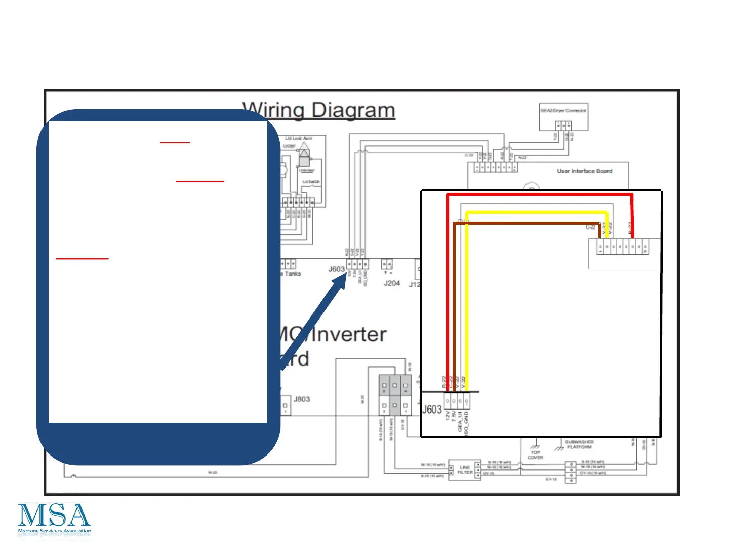
Check from the J603
connecter on the board. Look
for approximately 12 VDC
from the Red wire pin 4 to the
Yellow wire pin 1. And also
there should be approximately
7.5 VDC from the Brown wire
pin 3 to the Yellow wire pin 1.
If either of these voltages are not
present, replace the inverter
board.
If they are present and the UI
board is not coming on, replace the
UI board.
Diagnostics From The Board
UI Logic Board Voltage
UI Board
96
 Loading...