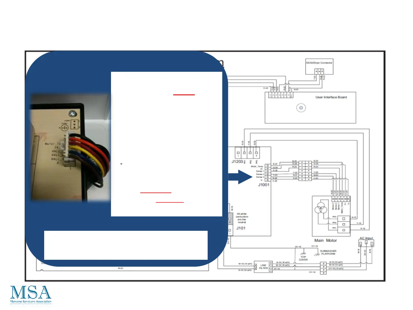
Diagnostics From The Board
Testing the RPS/Hall Sensor
The Hall Sensor can be
check from the J1001
connector.
With the power to the machine
on, and the connector plugged
in, you can see with your multi-
meter 0 – 12vdc signal from “P-
” to any one of the 3 HALL
wires on the inverter board
when you very slowly move the
basket. CAUTION: there is a
potential of -170vdc from
earth ground to “P”.
CAUTION: BE SURE TO USE YOUR
ELECTRICALLY RATED GLOVES.
98
 Loading...