Page 14 Chapter 1 — Installation and Initial Setup
number of bars is increased when you turn the screw coun-
terclockwise.) The optical bridge has now been balanced.
6. Place the HEAT switch back in the OPERATE position.
7. Run the instrument through another Pacer cycle. (Momen-
tarily press the INITiate switch.)
The letter “P” will light, and the displays will be frozen for sev-
eral minutes as the cycle proceeds. At the end of that time,
the “P” will go out, and the left-hand displays will read the
actual percent R.H. and temperature in the test chamber.
8. Use the SETPOINT switch to select 30% RH by pressing on the
upper or lower side of the switch as required.
The display will scroll, one decade at a time, to the desired
reading. Release the switch when that point is reached.
9. Run the chamber for at least one hour, until the water sur-
rounding the chamber assumes ambient laboratory tempera-
ture and the temperature equilibrates to ±0.2°C or better.
10. Use the SETPOINT switch to select 00.0 %RH and allow 30 to
45 minutes for the chamber to dry down.
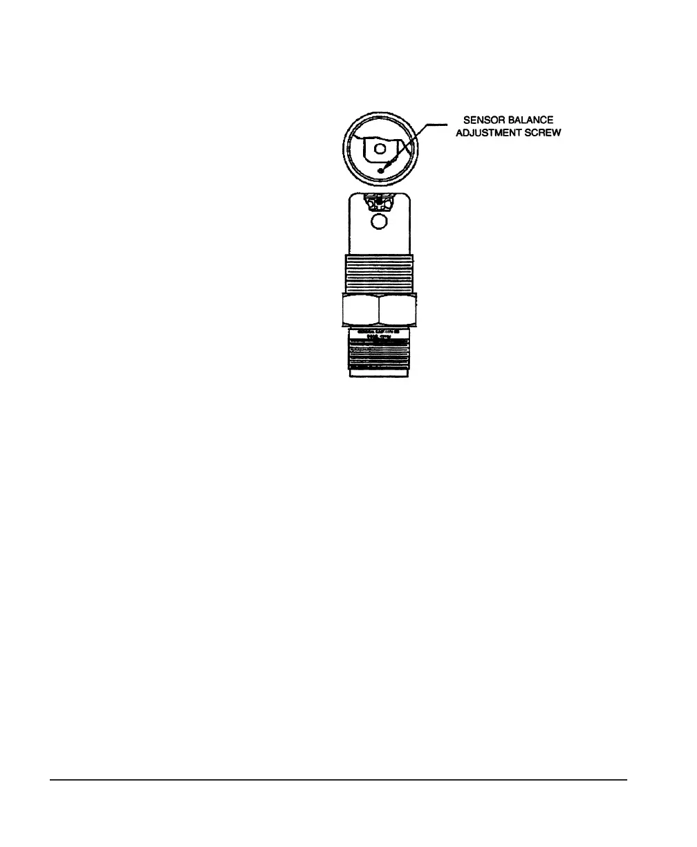
Figure 6 — 1111H Sensor Balance Adjustment Screw Location