iBox/iBox Kit
Installation and Maintenance Guide
GE Grid Solutions
994-0047-5.10-4 GE Information
LED Descriptions
Overview
You can verify the iBox is operating properly by inspecting the LEDs on the iBox
chassis.
Description
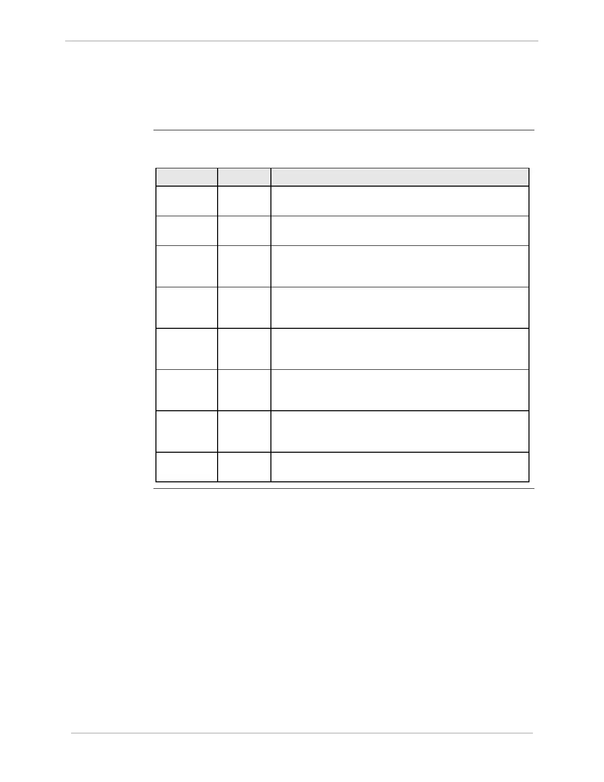
The iBox has the following LED indicators, all of which are GREEN.
LED Location Description
PWR Top left The POWER LED remains lit when the iBox is receiving
power.
RUN Top left The RUN LED flashes to indicate CPU bus activity. Brightness
indicates more CPU bus activity.
TX1 – TX3 Left side The TRANSMIT LED flashes when the iBox is transmitting to
an outside device. There are three transmit LEDs, one for
each communication port.
RX1 – RX3 Left side The RECEIVE LED flashes when the iBox is receiving a signal
from an outside device. There are three receive LEDs, one
for each communication port.
RS1 – RS3 Left side The Request to Send (RTS) LED only works on systems
configured for RS-232 communications. There are three RTS
LEDs, one for each communication port.
CS1 – CS3 Left side The Clear to Send (CTS) LED only works on systems
configured for RS-232 communications. There are three CTS
LEDs, one for each communication port.
CD1 – CD3 Left side The Data Carrier Detect (DCD) LED only works on systems
configured for RS-232 communications. There are three
DCD LEDs, one for each communication port.
I/P1 – I/P8 Right side Each of the iBox’s eight Digital Inputs (DI) has a LED that
remains lit when the DI is receiving a wetting voltage.